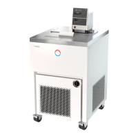
Proline Kryomats
YAUE0007 / 2/26/2009 Contents 5
7.5.5 Activating external control .............................................................................................................................46
7.5.6 Current consumption from the mains..............................................................................................................48
7.5.7 Setting the date and time (Command).............................................................................................................49
7.5.8 Display resolution setting (Command) ...........................................................................................................50
7.6 SPECIAL SETTINGS ...................................................................................................................................................51
7.6.1 Defining the type of start mode.......................................................................................................................51
7.6.2 Defining temperature limits............................................................................................................................52
7.6.3 Setpoint offset operating mode........................................................................................................................53
7.6.4 Restoring works settings.................................................................................................................................54
7.6.5 Setting the volume of the acoustic signals.......................................................................................................55
7.6.6 Entering the offset of the internal temperature probe.....................................................................................55
7.6.7 Restoring the works setting of the internal temperature-probe offset.............................................................56
7.6.8 Entering the offset of the external temperature probe ....................................................................................57
7.6.9 Restoring the works setting of the external temperature-probe offset ............................................................57
7.7 GRAPHICAL DISPLAY OF TEMPERATURE MEASUREMENTS (COMMAND)...................................................................58
7.8 PROGRAMMER (PGM ONLY COMMAND) .................................................................................................................60
7.8.1 Program example............................................................................................................................................60
7.8.2 Selecting and starting the program (Start, Hold, Stop) ..................................................................................62
7.8.3 Interrupting, continuing or terminating the program (Hold, Continue, Stop)................................................63
7.8.4 Creating or modifying a program (Edit).........................................................................................................64
7.8.5 Defining the number of program loops (Loops) .............................................................................................68
7.8.6 Viewing the program sequence as a graph (Graph).......................................................................................68
7.8.7 Obtaining information on a program (Info)....................................................................................................69
7.9 RAMP FUNCTION......................................................................................................................................................70
7.10 TIMER FUNCTION (COMMAND)................................................................................................................................71
7.11 CONTROL PARAMETERS...........................................................................................................................................72
7.11.1 Internal control variable (integral measurement probe)................................................................................73
7.11.1.1 Proven settings for control parameters and pump (integral measurement probe)...................................73
7.11.2 External control variable (External measurement probe) ..............................................................................73
7.11.2.1 Steps for setting the control parameters for external control ..................................................................74
7.12 ALARMS, WARNINGS AND ERRORS .........................................................................................................................75
7.12.1 Overtemperature protection and checking......................................................................................................75
7.12.2 Low-level alarm and low-level checking.........................................................................................................77
7.12.3 High-level settings ..........................................................................................................................................77
7.12.4 High-level warning or alarm ..........................................................................................................................78
7.12.5 Pump-motor supervision: Overload or blockage............................................................................................79
7.12.6 Pump-motor supervision: Dry running...........................................................................................................79
7.12.7 Compressor Overtemp....................................................................................................................................80
7.12.8 Three-phase current........................................................................................................................................80
7.12.9 Fault list „Alarms and Warnings“..................................................................................................................81
7.13 RS 232/ RS 485 INTERFACE.....................................................................................................................................84
7.13.1 Connecting cables and interface test RS 232..................................................................................................84
7.13.2 Protocol RS 232..............................................................................................................................................84
7.13.3 Connecting cable RS 485................................................................................................................................85
7.13.4 Protocol RS 485..............................................................................................................................................85
7.13.5 Write commands (Data commands to the thermostat)....................................................................................86
7.13.6 Read commands (Data requested from the thermostat)..................................................................................87
7.13.7 Error messages ...............................................................................................................................................89
7.13.8 Driver software for LABVIEW®.....................................................................................................................89
8 INTERFACE MODULES............................................................................................................................................90
8.1 INSTALLING OF MODULES .......................................................................................................................................90
8.2 MENU STRUCTURE FOR ALL MODULES (ONLY COMMAND) ......................................................................................91
8.3 SERIAL INTERFACES RS232/ 485.............................................................................................................................92
8.4 ANALOGUE MODULE................................................................................................................................................92
8.5 CONTACT MODULE ..................................................................................................................................................93
8.5.1 Contact module LRZ 915 with three inputs and three outputs........................................................................93
8.5.2 Namur-Contact module LRZ 914 with only one input and one output............................................................94

 Loading...