LAUNCH X-631/X-631+ Wheel Aligner Structures
2-3
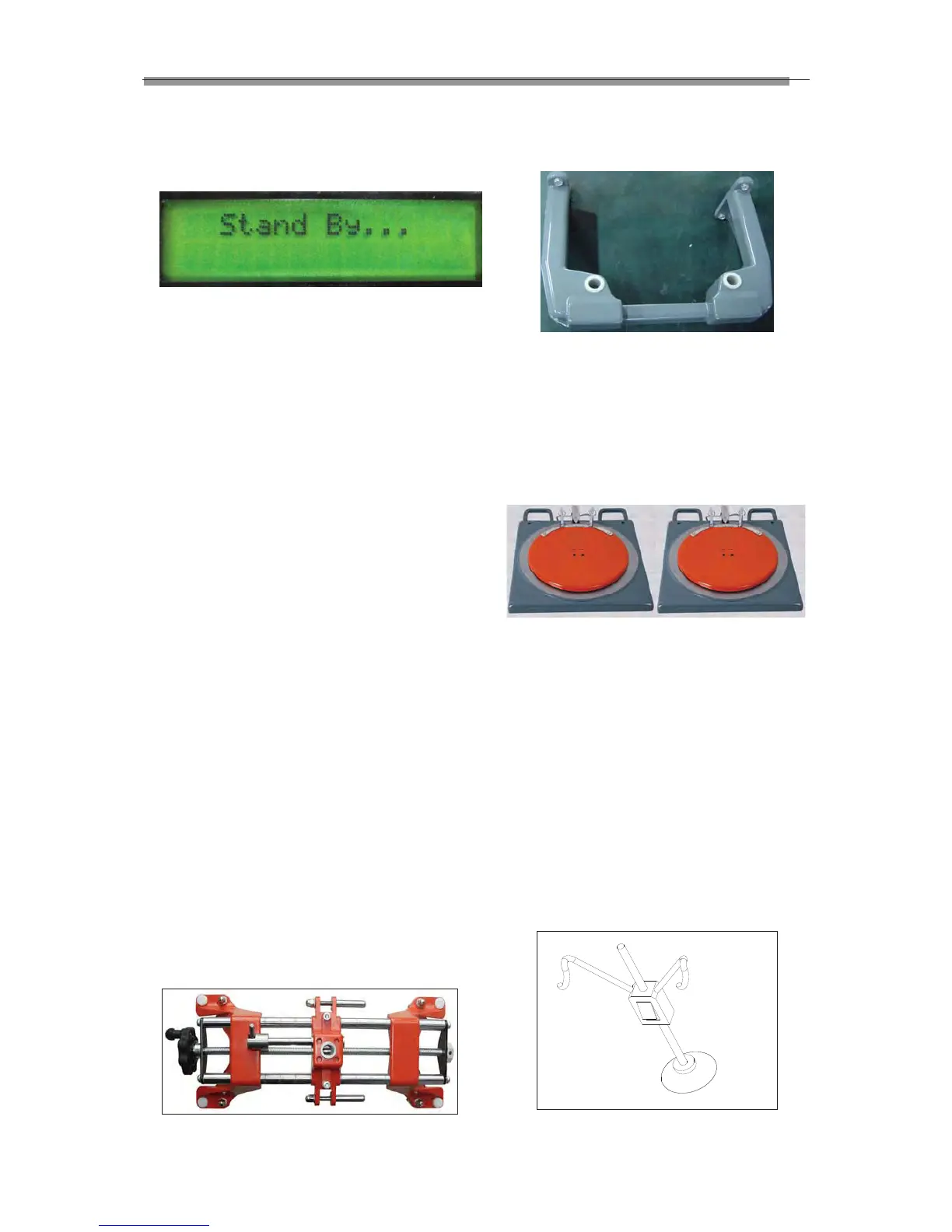
[Display Standby status]: “Stand By…” is displayed
on LCD. It indicates that the probe rod is in standby
mode for saving electricity. The standby mode can be
switched to normal working mode as shown in
Fig.2.14.
Fig.2.14
Button area includes 5 buttons:
[Backlight]: Key to switch on/off the backlight of LCD.
[Next]: To perform the test according to the default
sequence (Select Vehicle Model Run-out
Compensation Kingpin Measurement Rear
Axle Measurement Front Axle Measurement
Print Report Form ) of the system.
[Previous]: To return to the previous operating
procedure during test.
[Run-out compensation]: It is the special key-press for
run-out compensation operation.
[Power switch]: Switch on/off the battery power
supply of the probe rod.
There is a 9V power supply socket on the side wall of
the probe rod box. It is used for charging the battery
of the probe rod. When the electricity quantity of the
battery is full, the charging circuit will automatically
stop charging.
Caution! Make sure to turn off the power of the
probe rod before charging it. The probe rod is a
precision component; please handle it with care
to ensure measuring accuracy.
Wheel Clamps
X-631/X-631+ has 4 wheel clamps (see Fig.2.15).
Turn the adjusting knob to adjust the span between
wheel claws, and then attach the clamp to the wheel
rim. Adjust the knob to make the wheel clamp fixed
on wheel rim tightly. Use the wheel clamp tie to bind
the wheel clamp and the wheel rim together.
The installation of wheel clamp is crucial to the test
result. The claws should be in even contact with the
wheel rim without touching the lead weight.
Avoid hitting during operation. Otherwise, distortion
may be caused and the test result may be influenced.
Fig.2.15
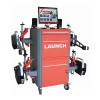
Wheel Clamp Hanging Bracket
X-631/X-631+ wheel aligner is equipped with 4 wheel
clamp hanging brackets as shown in Fig.2.16.
Fig.2.16
After unpacking, it is necessary to install these 4
hanging brackets on left and right side wall of the
cabinet.
Turntables
X-631/X-631+ has two mechanical turntables
(standard configuration, see Fig.2.17).
Fig.2.17 mechanical turntables
When testing, the turntables should be placed at the
front wheel position of vehicle on the lift.
Use the lock pin to lock the turntable before driving
the vehicle on. Pull out the lock pin after the vehicle is
stopped and the front wheels are at the center of the
turntables.
While testing, try your best to keep the vehicle front
wheel at the center of the turntable.
Steering Wheel Holder
X-631/X-631+ has a steering wheel holder as shown
in Fig.2.18. Use the steering wheel holder to lock the
steering wheel according to the tips on the screen.
Fig.2.18 Steering wheel holder