LAUNCH X-631/X-631+ Wheel Aligner Operation Instructions
4-1
Operation Instructions
Preparation
I. Drive the vehicle onto the lift or over the pit, so
that the front wheels are centered to the
turntables; Apply hand brake to ensure safety. To
prevent the turntable from turning, lock the
turntables with the lock pins before driving the
vehicle; release the lock pins after the vehicle is
well-positioned.
II. Ask the owner for vehicle drivability problems and
symptoms, wheel alignment history, and find out
vehicle information such as make, model and
year, etc.
III. Check each chassis part carefully, include dust
cover, bearing, rock arm, tripod-ball, shock
absorber, tie rod ball and steering mechanism,
for any loose or wear. Then check to see if the
tire pressure and treads of the left and right
wheels are alike.
IV. Install the wheel clamps on the four wheels in
turn and turn the knobs to lock the wheel clamps.
The claws of the wheel clamp should be fixed on
the external or internal edge of the rim according
to the practical condition. Ensure equal depth for
each claw and avoid attaching it on the distorted
area.
V. Install the probe rods on the pin
bushes of
wheel clamps as shown in Fig.4.1.
Fig.4.1
VI. Level the probe rod by adjusting the bubble in the
level gauge to the center position.
VII. Plug the power cable of the Wheel Aligner into a
standard power outlet of 3PIN. Switch on the
power supply of the cabinet and start the
computer.
VIII. Place the steering wheel holder on the driver seat;
and press the handle to lock the steering wheel.
IX. Put the brake pedal depressor between the brake
pedal and the driver seat to keep the brake
applied.
Operation procedures
Turn on the power switch, start the computer and
enter the main interface of the measurement program.
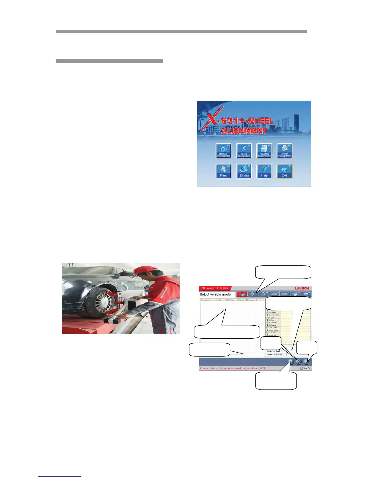
The screen displays the main function menu. There
are 8 functions available in the main menu: [Standard
Measurement], [Quick Measurement], [Additional
Measurement], [System Management], [Print], [2D
Interface/3D Interface], [Help], and [Exit]. See Fig.4.2
Fig.4.2
Standard Measurement
Click [Standard Measurement] in the interface as
shown in Fig.4.2. The screen system will enter the
standard measurement interface.
Select Vehicle Model
Before alignment, the standard data of the vehicle
model must be selected first. The interface is as
shown in Fig.4.3:
Fig.4.3
[Next]: To perform the test according to the default
sequence (Select vehicle model
ė Run-out
compensation
ė Kingpin measurement ė
Rear axle measurement ė Front axle
measurement
ėPrint report form ) of the system.
Next
Help
Quick search
Commonly used data list
Navigation column
Tire parameter
Selected from
standard data