LAUNCH X-631/X-631+ Wheel Aligner Operation Instructions
4-16
According to the prompts on the screen, install 4 probe
rods on the wheels respectively, and then adjust them
level. Click [NEXT] after finished.
Fig.4.51
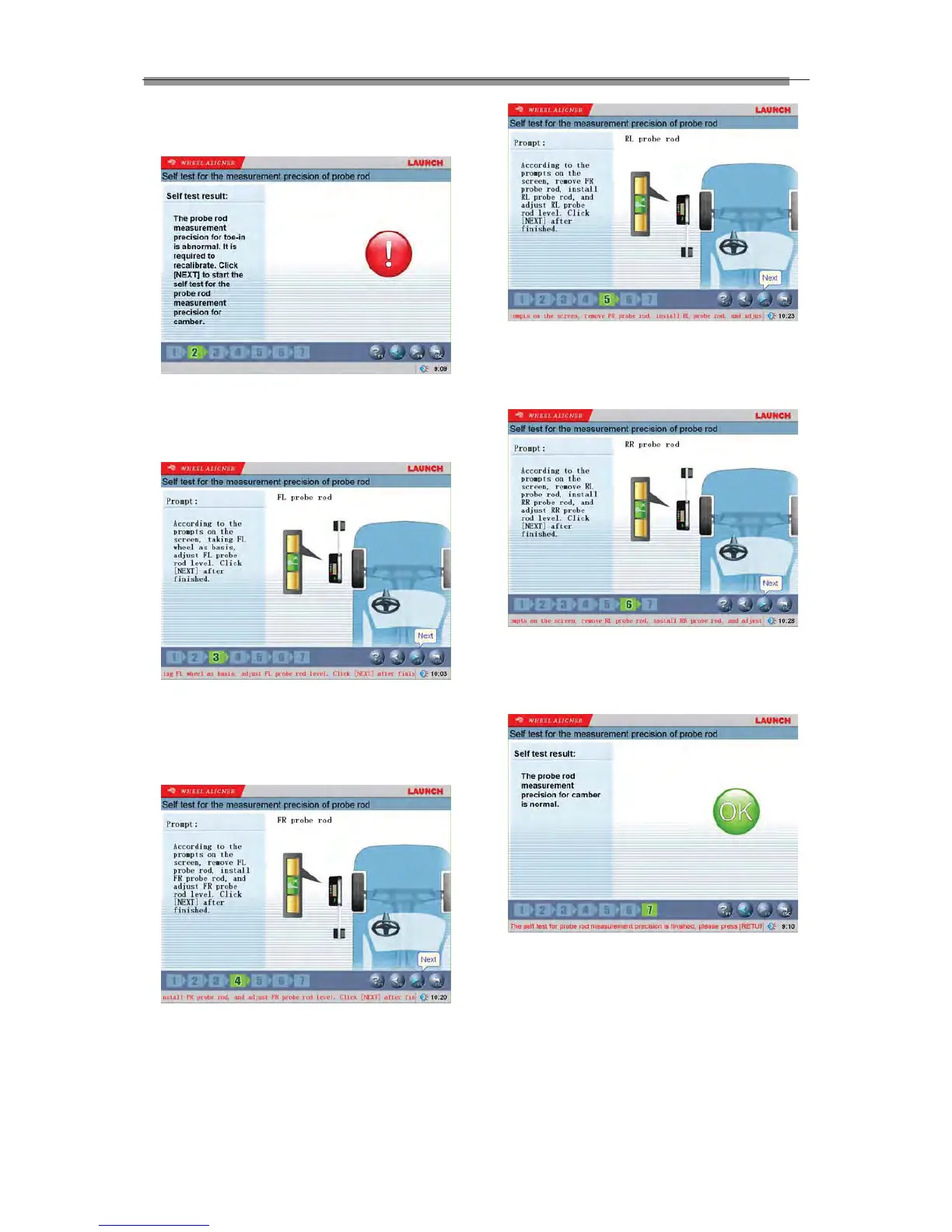
The screen will prompt whether the toe-in
measurement accuracy of 4 probe rods is normal or
not. If not, it is required to recalibrate.
Fig.4.52
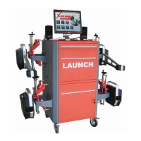
According to the prompts on the screen, take FL wheel
as reference, install FL probe rod on FL wheel, and
then adjust the probe rod level. Click [NEXT] after
finished.
Fig.4.53
Remove FL probe rod, install FR probe rod on FL
wheel, and then adjust the probe rod level. Click [NEXT]
after finished.
Fig.4.54
Remove FR probe rod, install LR probe rod on FL
wheel, and then adjust the probe rod level. Click [NEXT]
after finished.
Fig.4.55
Remove RL probe rod, install RR probe rod on FL
wheel, and then adjust the probe rod level. Click [NEXT]
after finished.
Fig.4.56
The screen will prompt whether the camber
measurement accuracy of 4 probe rods is normal or
not. If not, it is required to recalibrate.
Caution:
This function does not need calibration frame, it can be
performed on any one of vehicles.
Probe Rod Update
In the interface of [Probe Rod Maintenance], please