LAUNCH X-631/X-631+ Wheel Aligner Operation Instructions
4-20
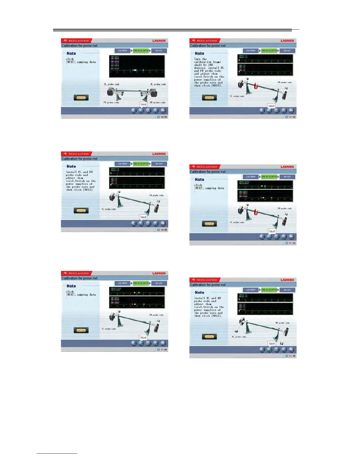
Fig.4.73
According to the prompts on the screen, please click
[NEXT] button to sample data. The interface is as
shown in Fig.4.74.
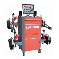
Fig.4.74
According to the prompts on the screen, install FL
and FR probe rods and adjust them level. Switch on
the power supplies of the probe rods, and then click
[NEXT] button. The interface is as shown in Fig.4.75.
Fig.4.75
According to the prompts on the screen, please click
[NEXT] button to sample data. The interface is as
shown in Fig.4.76.
Fig.4.76
According to the prompts on the screen, turn the
calibration frame shaft by 180 degrees, install FL and
FR probe rods and adjust them level; switch on the
power supplies of the probe rods, and then click
[NEXT]. The interface is as shown in Fig.4.77.
Fig.4.77
According to the prompts on the screen, please click
[NEXT] button to sample data. The interface is as
shown in Fig.4.78.
Fig.4.78
According to the prompts on the screen, install RL
and RR probe rods and adjust them level; switch on
the power supplies of the probe rods, and then click
[NEXT]. The interface is as shown in Fig.4.79.