Do you have a question about the LAUREL LAUREATE 2 Series and is the answer not in the manual?
Explanation of symbols used for safety warnings and electrical connections.
Information on the meter's operating environment requirements.
Wiring details for power and digital control inputs.
Wiring for various signal input types.
Wiring information for load cell meter inputs.
Wiring details for RTD and resistance input connections.
Wiring information for thermocouple input connections.
Wiring for setpoint controller outputs.
Wiring for RS232 and RS485 serial communication interfaces.
Wiring for analog output signal connections.
Steps to detach the rear panel from the meter casing.
Procedure for accessing and replacing internal electronic boards.
Guide for installing the meter into a panel cutout.
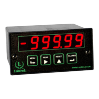
Identification of keys on the meter's front panel.
How to disable or enable front panel access for security.
Explanation of key functions during normal meter operation.
Details key functions and navigation within the meter's menu system.
Instructions for using a jumper to control menu access.
Method to enable/disable menu items via software settings.
Overview of the three available methods for scaling meter readings.
Explanation of internal counts and their relation to displayed values.
Method for enhancing display resolution by adjusting scaling factors.
Details jumper settings for specific meter board revisions.
Scaling and offset settings for DC voltage and current measurements.
Configuration for current shunt measurements using scaling methods.
Setup for load cell inputs using excitation and ratio settings.
Key sequences for input selection and basic meter setup.
Key sequences for configuration, filtering, and decimal point settings.
Key sequences for setting scale, offset, and calibration parameters.
How to select input ranges using jumpers for load cell/microvolt meters.
Configuring scale and offset for millivolt/microvolt readings.
Scaling setup for load cells and bridges using different methods.
Explanation of the 2-point scaling method for calibrating systems.
Lists available voltage ranges and corresponding jumper settings.
Lists available current ranges and corresponding jumper settings.
Jumper settings for AC/DC coupling selection.
Details the signal connections for the AC True RMS board.
Explanation of scaling for AC RMS measurements and current transformers.
Best practices for input signal wiring to minimize noise pickup.
Jumper configuration for thermocouple types and open indication.
Discussion of potential errors in thermocouple measurements.
Explanation of how CJC is handled and potential errors.
Sources of error related to thermocouple wire variations.
Jumper settings for RTD types and resistance ranges.
Setting scale and offset for RTD resistance measurements.
Best practices for signal wiring to minimize noise in resistance measurements.
Details on 4, 3, and 2-wire hookup methods for RTD/resistance.
Procedure to compensate for lead wire resistance in 2-wire hookups.
How to view and modify alarm setpoints using front panel keys.
Setup for Alarm 1 & 2 relay modes, state, hysteresis, and trigger count.
Setup for Alarm 3 & 4 relay modes, state, hysteresis, and trigger count.
Configuring hysteresis values for individual alarms.
Configuring band deviation values for individual alarms.
Key sequences for configuring analog output signal and filtering.
Selection of analog output signal type (mA or V).
Setting the low and high displayed values for analog output scaling.
Overview of available serial communication boards (RS232, RS485, USB, Ethernet).
Using USB-to-RS485 converters for meter networking.
Steps for connecting and installing drivers for USB communication.
Jumper configurations for communication boards.
Details jumper settings for Ethernet, RS232, RS485, and converter boards.
Selection of transducer excitation outputs using jumpers.
Special features configured by jumpers on the power supply board.
Instructions for installing the Instrument Setup software on a PC.
Requirements for connecting the meter to a PC for setup.
Steps to establish communication between the meter and PC software.
Managing setup files (retrieving, editing, saving, downloading).
Configuring meter settings via software without a direct connection.
Requirements for performing custom curve linearization.
Initial steps and software execution for custom curve setup.
Methods for entering linearization data (text file, keyboard).
Entering linearization parameters using polynomial equations.
Using the meter keypad to switch between linear and custom curve modes.
Information on factory calibration and non-volatile memory storage.
Information on returning the meter for recalibration services.
Calibrating specific boards using Instrument Setup Software.
Calibration method for RTD/Ohms boards using scaling settings.
Specifications for the meter's display type, color, and range.
Technical details of the analog-to-digital conversion process.
Specifications related to common mode and normal mode noise rejection.
Input voltage and power consumption details for the meter.
Detailed specifications for DC voltage input ranges.
Detailed specifications for thermocouple input types and ranges.
Specifications for relay output options, including ratings and modes.
Specifications for the analog output option, including levels and accuracy.
Specifications for serial interface options (USB, RS232, RS485, Ethernet).
Operating and storage environmental conditions for the meter.
Defines key terms related to input signals, scaling, alarms, and control.
Defines terms related to serial communication, PC setup, and meter configuration.
Specifies conditions under which the warranty does not apply.
Outlines the buyer's sole and exclusive remedies under the warranty.
| Type | Digital Panel Meter |
|---|---|
| Display | LED |
| Input Type | Resistance, Temperature |
| Operating Temperature | 0°C to 50°C |
| Digital Interface | RS-485 |
| Analog Output | 4-20 mA, 0-10 VDC |