Page 6PROTECTOR® IV Top of Rail Installation, Operation & Maintenance Manual
Bars
The bars are designed to distribute grease to the gauge face of the rail. When applied properly, this reduces
83$%)$./&*d<*3$*/%*;&>*)5**/&)4*&54**6&V"/1*&"/;&)4*&1"21*&8"%*&.8&)4*&3"$6&54$%4&$/&3*)23/&5$66&*d)*/;&)4*&3"$6&
and wheel life, reduce noise and improve tracking through curves.
SITE SELECTION
INSTALLATION AND MAINTENANCE OF THE PROTECTOR IV SYSTEM REQUIRES PERSONNEL TO BE
ON-TRACK, INCLUDING BETWEEN THE RAILS. PRECAUTIONS MUST BE TAKEN TO ENSURE THAT
THERE WILL BE NO TRAFFIC WHILE DOING THIS WORK.
Proper site selection for the PROTECTOR IV is one of the most important considerations associated with
"%4$*?$/1&*S*%)$?*&83$%)$./&+"/"1*+*/)&+")*3$"6&;$#)3$>2)$./9&:4*/&#*6*%)$/1&"&#$)*&8.3&$/#)"66")$./@&.<)$+"6&
performance of the unit depends upon attaining as many of the following general considerations as possible:
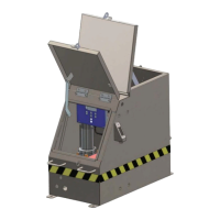
1. It should be positioned on level stable ballast. The base can be made from either cut wooden sleepers
L#2<<6$*;&$8&3*H2$3*;R&.3&"&%./%3*)*&<";9&B+>*;&)4*&>"#*&$/&)4*&>"66"#)&"/;&"Kd&)4*&%">$/*)&).&)4*&>"#*@&6"1&
screws are provided for a timber base.
2. Locate the unit as close to the curve in the track as possible. Avoid locating the unit inside a curve. This is
particularly important if noise reduction is the primary goal.
IT IS NOT RECOMMENDED TO INSTALL A UNIT IN A CURVE. THE EFFECT OF HAVING THE WHEELS
HUGGING THE HIGH RAIL CAUSES PREMATURE WEAR AND TEAR ON THE WIPING BARS. WIPING BARS
LOCATED ON THE LOW RAIL ARE LESS EFFECTIVE IN DEPOSITING GREASE. DO NOT INSTALL BARS
CLOSER THAN 100 ft. (30.5 m) TO AN INSULATED JOINT. THIS WILL MINIMIZE ANY POTENTIAL GREASE
BUILD-UP AT THE JOINT WHICH COULD AFFECT SIGNALING.
3. In areas with multiple curves, select a site in a short tangent section of track between curves. At this
location the grease material is carried in both directions and into adjacent curves.
4. Select a site where there is no pronounced railhead wear and railhead is in excellent condition. If transposed
.3&3*6"(&3"$6&5$)4&+")*3$"6&V.5&./&)4*&0*6;&#$;*&$#&<3*#*/)@&)4*&V.5.26;&>*&13.2/;&.S&")&)4*&2/$)&#$)*@&
before attempting to install the wiping bars.
5. Select a site where the tie conditions are good and install the unit as close to zero grade as possible.
J/#)"66$/1&)4*&2/$)&$/&"&6.%")$./&54*3*&)4*&)"/T&.2)6*)&$#&6.5*3&)4"/&)4*&)3"%T&5$66&3*;2%*&*K%$*/%(9
6. '*6*%)&"&#$)*&)4")&<3.?$;*#&"%%*##&).&)4*&2/$)&8.3&3*126"3&+"$/)*/"/%*&"/;&3*066$/19
7. Install the tank far enough from the track to safely clear the operation of ballast regulators, snow plows, and
.)4*3&)3"%T&*H2$<+*/)@&>2)&%6.#*&*/.214&).&"66.5&)4*<<6(&4.#*&).&>*.3)*/*;&8.3&+"d$+2+&*K%$*/%(9
8. Select a site where power source can be easily routed to the unit. Be sure the length and size of the power
cable does not cause an unacceptable line loss. In remote locations with no AC power availability, the solar
panel option is recommended.
Note: Outside AC electrical currents from overhead power wires, third rail power or signal system power sources
can interfere with the wheel sensor detection capabilities.
9. Avoid selecting a site where trains routinely slow down or come to a complete stop.
10. Site selection should be in an area which will discourage acts of vandalism.
11. The grease works best where both the rails and wheels are clean.