DMA882S Digital Stepper Drive User Manual
Page | 10
AC
A+
A-
AC
1
5
6
Power &
Motor Connector
Controller
Control Signal
Connector
4
PUL+
1
DIR+ 3
PUL-
DIR-
2
4
ENA+ 5
ENA-
6
5-24VDC
Step
Direction
Enable
Fault
5-24VDC
ALM+
1
2
ALM-
Status Signal
Connector
36-70VAC or 50-90VDC recommended,
leaving rooms for voltage fluctuation and
back EMF of the motor
2
3
B+
B-
DMA882S
Stepper
Motor
Figure 10: Typical connection
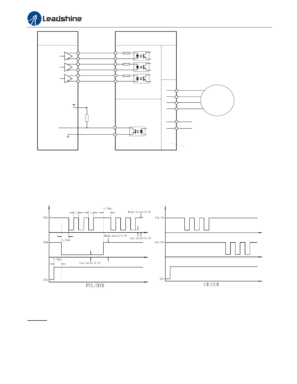
10. Sequence Chart of Control Signals
In order to avoid some fault operations and deviations, PUL, DIR and ENA should abide by some rules, shown as
following diagram:
Figure 11: Sequence chart of control signals
Remark:
a) t1: ENA must be ahead of DIR by at least 5s. Usually, ENA+ and ENA- are NC (not connected). See
“Connector P1 Configurations” for more information.
b) t2: DIR must be ahead of PUL effective edge by 5s to ensure correct direction;
c) t3: Pulse width not less than 2.5s;
d) t4: Low level width not less than 2.5s.