DMA882S Digital Stepper Drive User Manual
Page | 4
Warning: Don’t plug or unplug the P1 & P2 terminal block to avoid drive damage or injury when DMA882S
is powered on.
3.3 LED Light Indication
There are two LED lights for DMA882S. The GREEN one is the power indicator which will be always on generally.
The RED one is a protection indicator which will flash 1-2 times in a 3-second period, when protection enabled for a
DMA882S. Different number of flashes indicates different protection type (read section 11 for detail).
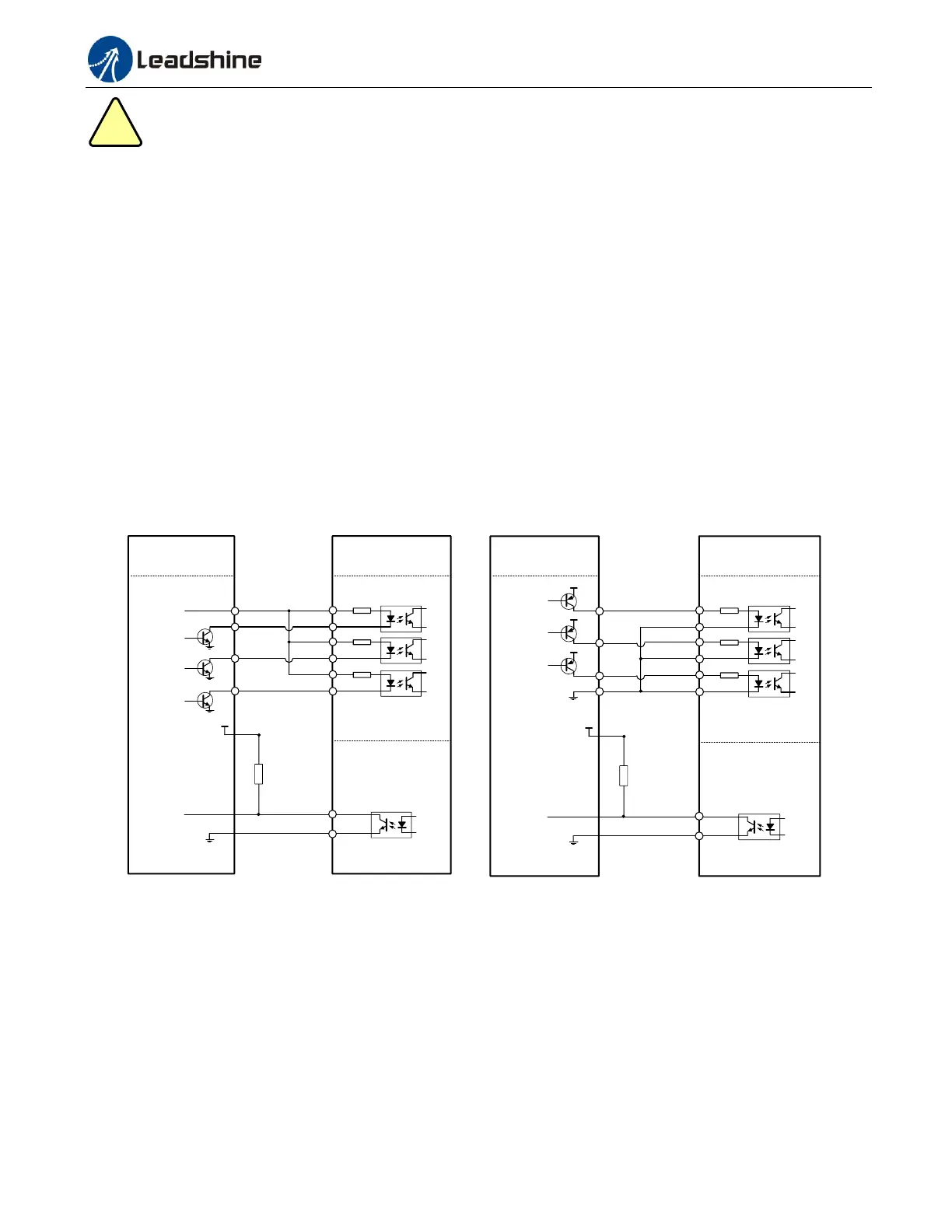
4. Control Signal Connector (P1) Interface
The DMA882S can accept differential and single-ended inputs (including open-collector and PNP output). The
DMA882S has 3 optically isolated logic inputs which are located on connector P1 to accept line drive control signals.
These inputs are isolated to minimize or eliminate electrical noises coupled with the drive control signals. Recommend
using line drive control signals to increase noise immunity for the drive in interference environments. In the following
figures, connections to open-collector and PNP signals are illustrated.
Controller
Control Signal
Connector
VCC = 5-24V
5V recommended
Fault
5V
ALM+ 1
2
ALM-
Status Signal
Connector
DMA882S
PUL+
1
DIR+ 3
PUL-
DIR-
2
4
ENA+ 5
ENA-
6
5-24V
5V recommended
Step
Direction
Enable
Controller
Control Signal
Connector
PUL+
1
DIR+ 3
PUL-
DIR-
2
4
ENA+ 5
ENA-
6
VCC = 5-24V
5V recommended
Step
Direction
Enable
VCC
VCC
VCC
Fault
5V
ALM+ 1
2
ALM-
Status Signal
Connector
DMA88S
Figure 2: Connections to open-collector signal Figure 3: Connections to PNP signal
(common-anode) (common-cathode)
5. Motor Connection
The DMA882S can drive 2-phase and 4-pahse bipolar hybrid stepper motors with 4, 6, or 8 wires.
5.1 Connections of 4-lead Motor
The 4 lead motors are the least flexible and easy to connect. And the Speed – torque of motor depends on winding
inductance. The output current from drive that is multiply the specified phase current by 1.4 to determine the peak