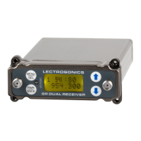
SRa5P and SRa Dual Receivers
LECTROSONICS, INC.
8
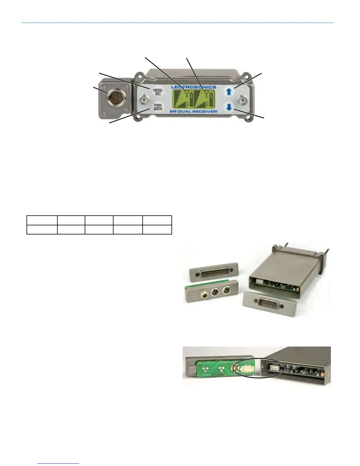
Front Panel Controls and Functions
Audio Outputs
Inadditiontotheaudiooutputsontherearpanel,the
front panel of the receiver provides a second set of
outputs through a 5-pin connector. For cameras with
onlyoneaudiochannelenabledintheslot,Itallows
both audio channels to be connected through externals
cables.
The TA5M connector provides two balanced outputs
with the following pinouts:
Pin 1 Pin 2 Pin 3 Pin 4 Pin 5
Shields CH1+ CH1– CH2+ CH2–
LCD Screen
Abacklit,graphics-typeLiquidCrystalDisplayisused
to set up and monitor the receiver. The Main Window
shown here is used during normal operation, to display
RF and audio levels, transmitter battery status, pilot
tone status and diversity activity for both receivers.
MENU/SEL Button
This button is used to select menu items and enter
setup screens during setup.
PWR/BACK Button
PressthePWR/BACKswitchtoturnthepoweron.
Press and hold it until the display goes blank to turn
poweroff.Italsofunctionsasa“back”buttonwhilenavi-
gating the various menus and setup screens to return to
the previous screen or menu item.
The firmware “remembers” whether the receiver was
turned on or off after power is disconnected, and it
returns to that state when power is restored. This allows
the receiver to power up and down as the camera is
turned on and off.
PressthePWR/BACKbuttonfromtheMainWindowto
briefly display the external power voltage.
UP/DOWN Arrow Buttons
TheUPandDOWNarrowbuttonsareusedtoselect
variousoptionsandadjustvaluesinthesetupscreens,
and provide secondary functions such as locking out
the panel to guard against accidental changes.
Rear Panel and Adapters
Several different panel adapters are available to config-
ure the receiver for use with popular camera slots and
for stand-alone use. The adapters are retained by two
screws through the side panel of the housing, making
them easy to install.
Power and audio connections are made through mating
connectors on the adapter and receiver main circuit
boards.
DOWN Button
MENU/SELECT
Button
POWER/BACK
Button
UP Button
Receiver 1 Receiver 2
LCD Main Window with two channels shown
Audio
Output