Leica ComGate10, Description of the System
15
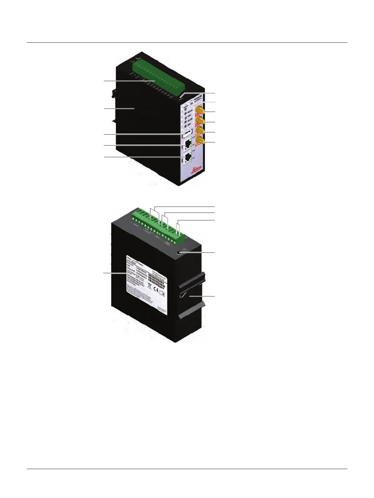
2.4 System Components
2.4.1 ComGate10
Main components
a) Terminal block
b) SIM card compartment
c) USB host connector for SmartWorx Viva
and Captivate instruments or another
sensor by the USB-serial converter
(RS232)
d) Ethernet switch for local network
e) Ethernet connector for connecting to
the Internet
f) Mini button to reset the ComGate10
g) Status LEDs
h) Connector for first UMTS/LTE antenna
i) Connector for second UMTS/LTE
antenna (MIMO mode)
j) Connector for first WLAN antenna
k) Connector for second WLAN antenna
(MIMO mode)
a) Label
b) Galvanic isolated digital outputs.
The outputs show the difference on
DO1 and DO2. DO2 is switched auto-
matically, if any TPS instrument is
connected by ComBox Manager. DO1
can be used for warning signals.
c) Serial RS232 interface
d) Power supply
e) Connection to the ground. The connec-
tion is required to ensure ESD compat-
ibility.
f) DIN rail mounting
014111_002
a
d
f
g
h
j
i
k
e
c
b
006178_003
a
b
c
d
e
f