THROUGH DOVETAIL PROCEDURES
24
Chapter 8 Super Jig-12-18-24 User Guide
1
2
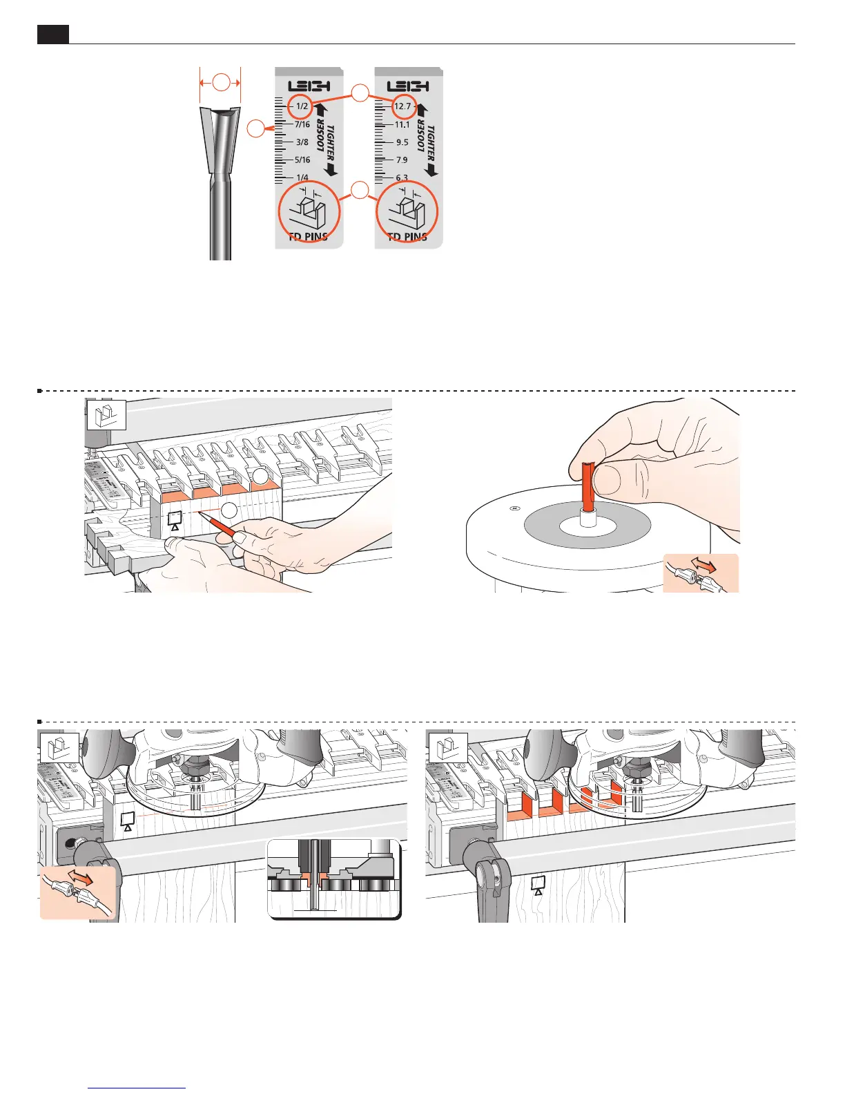
8-23 Clamp a test pin board against the left hand side stop,
outside face
o
away from the jig, with the top end flush under
the guides
.
Place the side edge of one of the finished tail boards horizontally
flush under the guidefingers and mark a thin pencil line part way
across the pin board
.
8-24 Unplug the router and remove the dovetail bit. Mount the
included No. 140-8 straight bit to the router.
8-25 Place the router on the finger assembly and adjust the router
until the bit tip is level with the center of the pencil line. Check
to make sure the bit rotates freely.
8-26 Rout out the waste between the pins. Check to make sure
no parts have been missed. See Chapter 15 "Hints and Tips" on
how to minimize tearout.
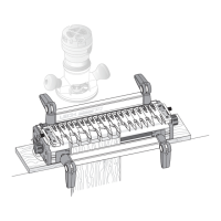
8-22 How the TD PIN Scales Work
The dimensions on the TD Pin scale
indicate the major width of the pin to be routed
. This matches the size of dovetail bit just
used to rout the tails
. The increment lines on the scale
➃
are spaced so that moving the finger assembly by one increment changes
the joint glue-line gap by just 0.005"[0,125mm]. Even better, a one quarter division movement changes the fit by 0.00125"[0,03mm],
a tiny one and a quarter thousandth of an inch! Once you achieve the desired joint fit, simply record the setting using the illustrations
at the end of this chapter.
2
1
4
3