53
SLIDING DOVETAILS
Chapter 13Super Jig-12-18-24 User Guide
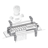
13-7 Marking Out: Do not mark the slot positions on the board
faces, Mark the edges of both slot boards together for perfectly level
shelves. Stay at least 7"[180mm] in from the ends for clamping
on this test project. 13-25 describes how to rout close to both ends.
Mark the narrow test slot board in the same way at several closely
spaced random spots. This board is used only for setup.
13-8 On the test slot board only, square the marks across the
face.
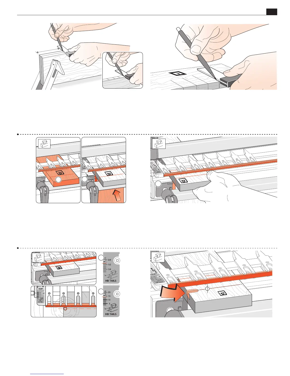
13-9 Mount the test slot board in the rear clamp, markings up
.
Mount a
3
⁄4"[20mm] thick
square-ended board vertically in
the front clamp against the side stop, with the top edge butting
the underside of the test board (yes, the 3⁄4"[20mm] thickness is
important).
2
1
13-10 Position and clamp the test board so that one of the edge
marks is in line with the outside edge of the vertical board
.
�
13-11 With the finger assembly (including the cross cut fence)
on the support brackets in the
H
HB TAILS mode, set the scale
to
9
⁄16"[14mm]
. The routed slot will be close to centred on the
slot line. Make sure the finger assembly is level and sitting flush on
top of the board.
�
�
13-12 Adjust the bit so the cut depth is about
5
⁄16"[8mm].
Rout from left to right maintaining light inward pressure of the
guidebush on the fence. Rout in only about 1"[25mm] and back
out again.
Do not lift the router.