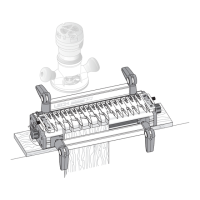
JIG ASSEMBLY, MOUNTING, AND USING THE CLAMPS
2
Chapter 1 Super Jig-12-18-24 User Guide
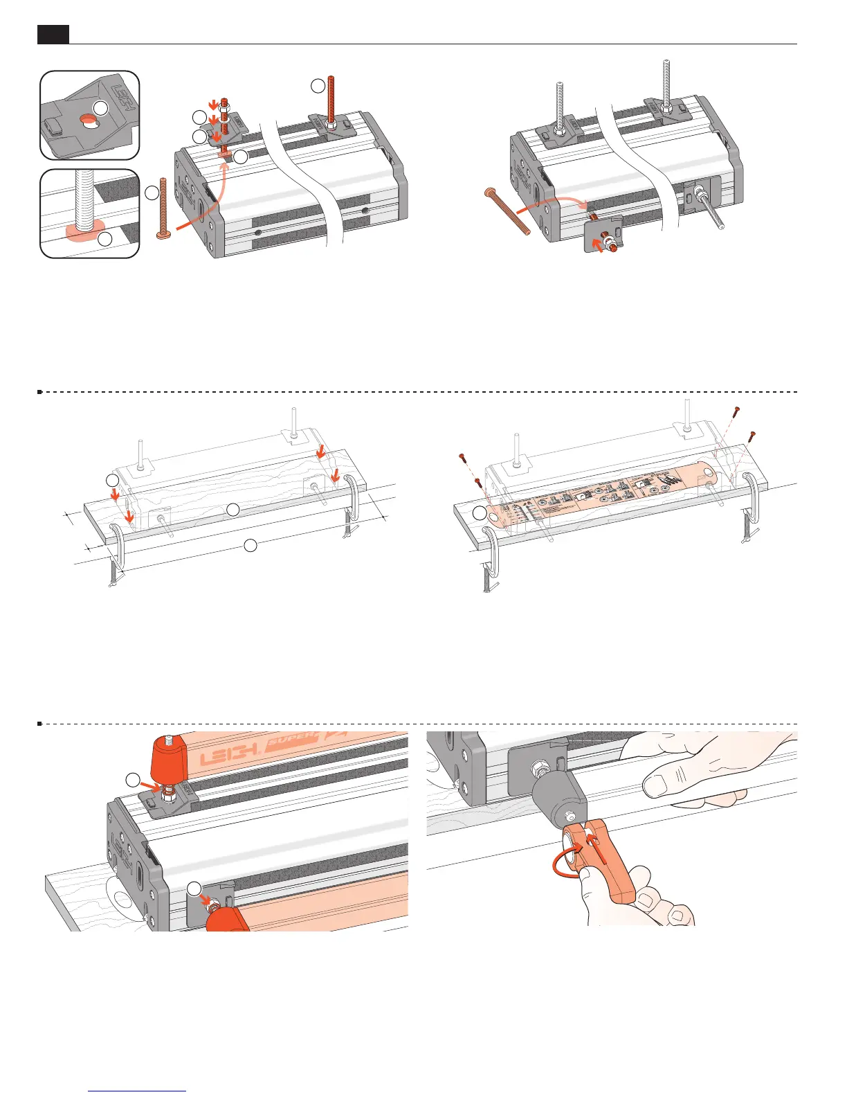
1-1 Install Side Stops Insert two clamp T-bolts through the
rear jig body holes
and place a “stepped” rear side stop over each
bolt
, using the rear part of the double-hole
. Make sure the
bolt's “T” is between the extrusion ribs
➃
. Don’t forget the steel
washer
➄
and use a ½"[13mm] wrench to tighten the nuts.
1
4
4
1
2
5
1-2 Insert the two front clamp T-bolts through the jig body
holes. Make sure the bolt's “T” is between the extrusion ribs.
Place a front side stop and steel washer over each bolt but only
finger-tighten the front nuts; you will need to index these to the
rear stops later.
1-3 Prepare a flat ¾"[20mm] mounting board (plywood or MDF),
at least 5"[125mm] wide. Length
: 26" for Super12, 32" for Super18,
40" for Super24 [660, 830 or 1000mm respectively]. Clamp it to the
front of your bench. Center the jig on the board, front face slightly
overhanging the board edge
. Mark the four hold down screw posi-
tions. Drill small pilot holes at a slight angle
.
2
3
5"
[125mm]+
1
1-4 Quick Reference Pull-Out Decide which end
of the jig you wish to access the “Quick Reference” instruction
pull-out and place the jig over the pull-out
. Using the screws
provided; screw the jig to the board. Make sure that the pull-out
slides freely.
1
1-5 Place four springs
and two clamp bars on the T-bolts.
Make sure the clamp bars move freely on the T-bolts.
1
1
1-6 Screw a clamp lever assembly onto each T-bolt.