Page 5
Outdoor Fan Clearances
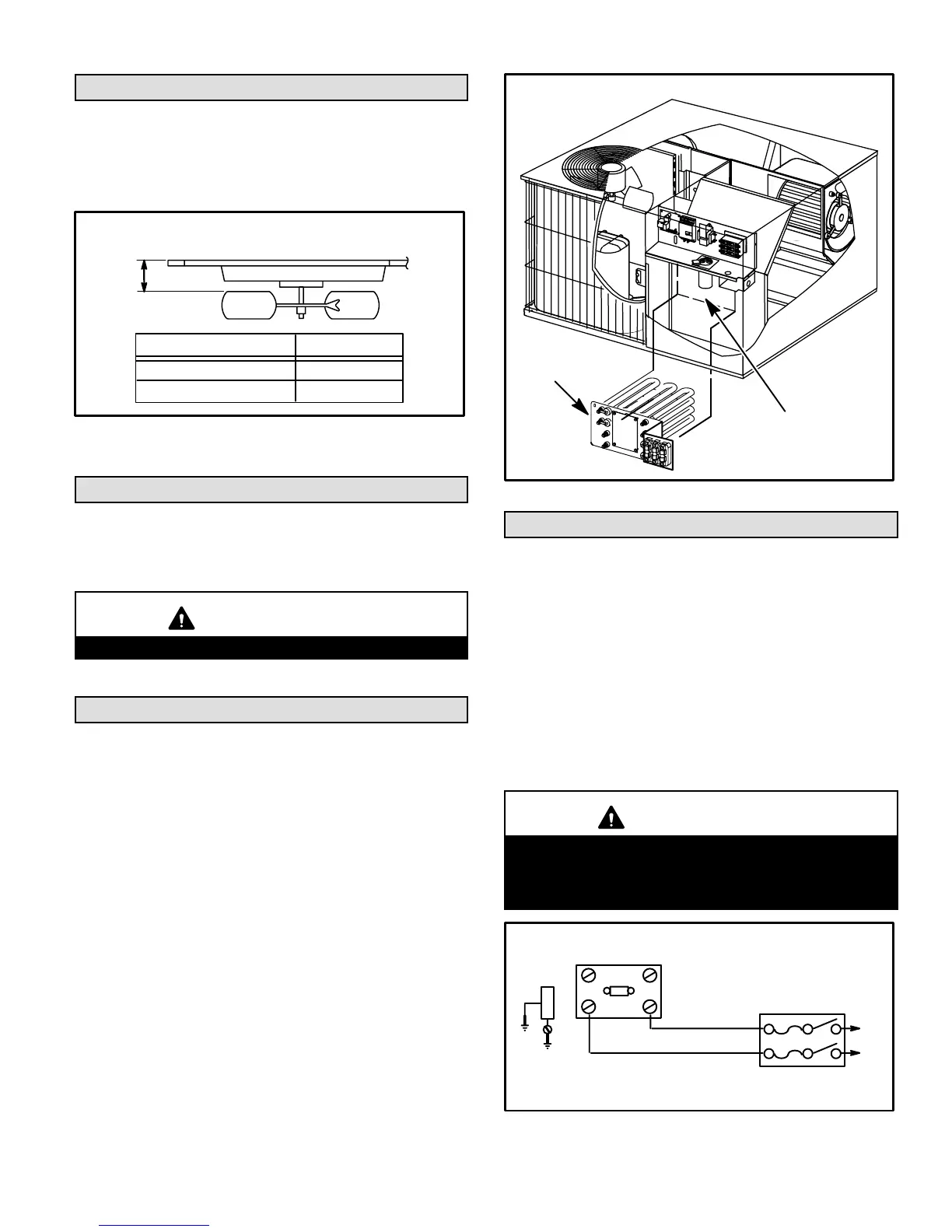
Figure 4 illustrates the critical measurements of the out
door fan system. This dimension should be checked and
fan adjusted accordingly anytime servicing of the outdoor
fan system is required.
OUTDOOR FAN CLEARANCES
FIGURE 4
A
UNIT MODEL NO. A
−024, −030
−036, −042, −048, −060
3"
3−1/2"
Compressors
Units are shipped with compressor mountings factory−ad
justed and ready for operation.
CAUTION
Do not loosen compressor mounting bolts.
Optional Electric Heat
The unit is fully equipped for heat pump operation without
auxiliary heat.
Installing Optional Electric Heat Section
1 − Disconnect power and open main control access.
2 − Disconnect the plug separating the high voltage
wire harness.
3 − Remove the high voltage wire harness plug and discard.
4 − Remove the heater blockoff by removing the four
screws holding it in place.
5 − Cut away insulation covering opening, using the hole
in the panel as a template.
6 − Insert the heater into the control panel and fasten in
the same mounting holes. See figure 5.
7 − Plug the heater wiring harness into the wire harness
on the control assembly.
8 − Field wiring of auxiliary heater is separate from unit
power supply. Wire power supply wiring for the heater
to appropriate connections on heater kit.
OPTIONAL ELECTRIC HEAT INSTALLATION
FIGURE 5
HEATER
BLOCKOFF
OPTIONAL
ELECTRIC
HEAT
Electrical
USE COPPER CONDUCTORS ONLY
All field wiring must be done in accordance with National
Electric Code recommendations, local codes and applica
ble requirements of UL or in accordance with Canadian
Electrical Code, local codes and CSA Standards. Power
wiring, disconnect means, and over−current protection are
to be supplied by installer. See unit rating plate for maxi
mum over−current protection, minimum circuit ampacity, as
well as operating voltage. The power supply must be sized
and protected according to specifications supplied. See
figure 6 for field connection of line voltage wiring and fig
ures 7 and 8 for typical wiring diagrams.
CAUTION
When connecting electrical power and control wir
ing to the unit, waterproof type connectors MUST be
used so that water or moisture cannot be drawn into
the unit during normal operation.
208/230 LINE VOLTAGE WIRING
NOTE − If 208 voltage is supplied, transformer connections must be
made.
L1
FUSED DISCONNECT SWITCH
(FURNISHED BY INSTALLER)
GROUND
LUG
L2
FIGURE 6
CONTACTOR
 Loading...