Page 8
Unit must be grounded with separate ground conductor.
The unit wiring diagram is located inside the unit access
panel. Low voltage control wiring are pigtail leads located
below the main control box and are color coded to match
the connection called out on the wiring schematic.
If any of the original unit wiring is replaced, the same size
and type wire must be used. Electrical wiring must be
sized to carry minimum circuit ampacity marked on the
unit. Each unit must be wired with a separate branch cir
cuit and be properly fused.
System Performance
For maximum performance of this heat pump system, the
operating temperatures and pressures should be
checked and superheat determined at Standard ARI test
conditions of 82_F outdoor − 80_F indoor dry bulb/67_F
wet bulb. If superheat measured deviates from values in
table below, refrigerant charge should be adjusted ac
cordingly for maximum performance.
Verify system performance using table 3 or table 4 as a
general guide. These tables should not be used for charg
ing the unit. Minor variations in these pressures may be
expected due to differences in installations. Significant
differences could mean that the system is not properly
charged or that a problem exists with some component in
the system. Used carefully, this table could serve as a use
ful service guide. Table 3 should be used when unit is
charged during the heating mode. If outdoor ambient is
below 45°F, run unit through defrost cycle first, wait 15
minutes for system pressures to stabilize, then take pres
sures. Data in table 3 is based on 70°F dry bulb return air.
Data in table 4 is based on 80°F dry bulb / 67°F wet bulb
return air. Allow unit operation to stabilize before taking
pressure readings.
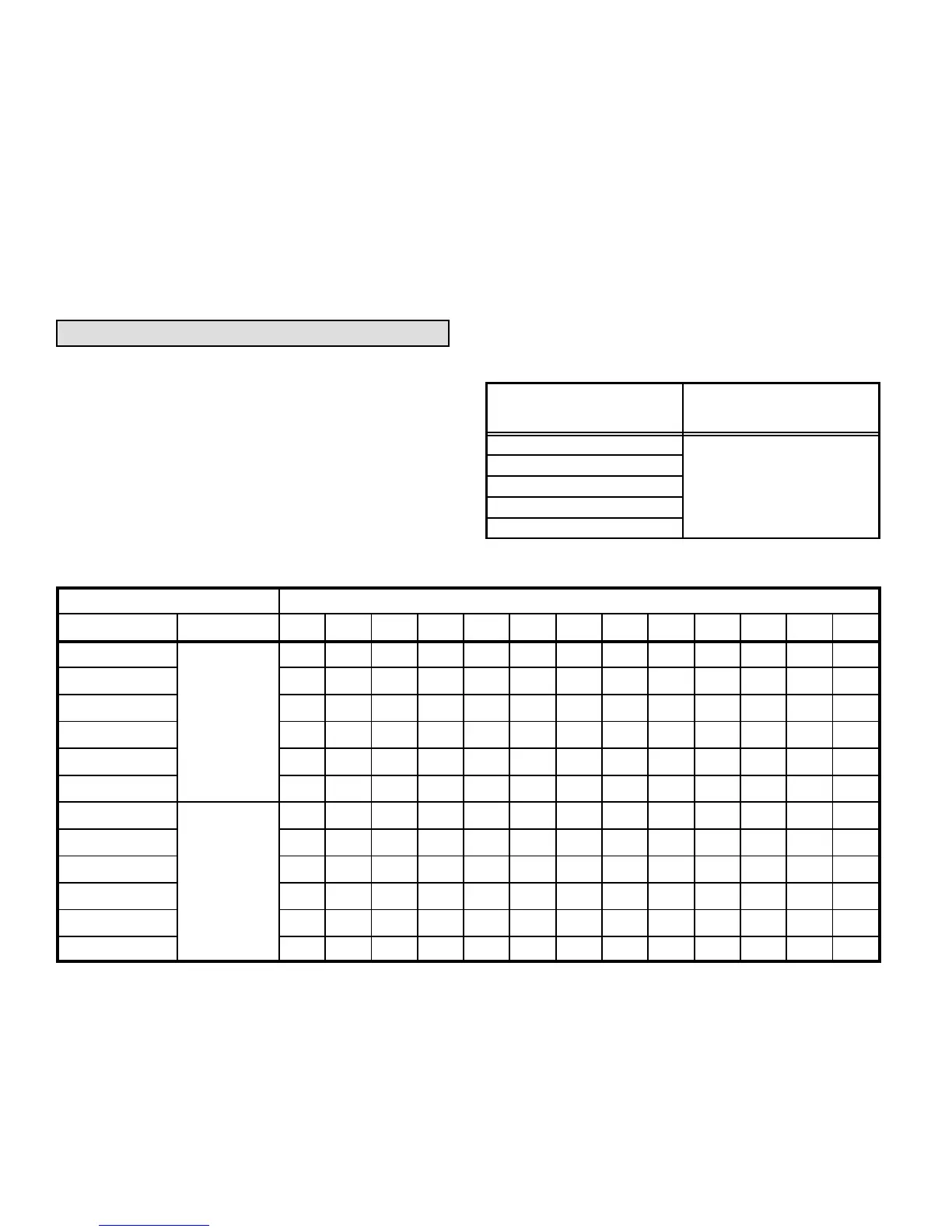
TABLE 2
SUCTION SUPERHEAT TABLE
UNIT MODEL NO.
SUCTION SUPERHEAT
82_F OD minus 80_F IDDB
/ 67_F IDWB
12CHP−030, −036
12CHP−024
12CHP−030
18 − 20_
12CHP−036
12CHP−042, −048, −060
TABLE 3
NORMAL OPERATING PRESSURES −− HEATING MODE
70°F db RETURN AIR AIR TEMPERATURE ENTERING OUTDOOR COIL (°F)
MODEL PRESSURE 0° 5° 10° 15° 20° 25° 30° 35° 40° 45° 50° 55° 60°
12CHP−024 17 20 24 28 33 38 43 49 55 62 69 74 81
12CHP−030 14 17 21 25 29 34 39 45 51 56 63 70 78
12CHP−036
14 17 21 25 29 34 39 45 51 56 63 70 78
12CHP−042
16 19 23 27 31 36 41 45 51 55 62 68 76
12CHP−048 15 18 22 26 30 35 40 45 51 55 62 68 76
12CHP−060 14 17 21 25 29 34 39 44 50 54 61 67 75
12CHP−024 181 191 200 209 219 228 237 247 256 265 275 284 293
12CHP−030 168 173 179 184 189 195 200 205 211 216 221 227 232
12CHP−036
165 172 178 184 191 197 203 210 216 222 229 235 241
12CHP−042
167 174 181 187 194 201 207 214 221 227 234 241 247
12CHP−048 203 211 220 229 237 246 255 263 272 281 289 298 307
12CHP−060 163 170 177 183 190 197 203 210 217 223 230 237 243
 Loading...