Page 9
TABLE 4
NORMAL OPERATING PRESSURES −− COOLING MODE
80°F db / 67°F wb
RETURN AIR
AIR TEMPERATURE ENTERING OUTDOOR COIL (°F)
MODEL PRESSURE 65° 70° 75° 80° 82° 85° 90° 95° 100° 105° 110° 115° 125°
12CHP−024 78 79 81 82 83 84 85 87 89 90 92 93 96
12CHP−030 78 79 81 82 83 84 85 87 89 90 92 93 96
12CHP−036
75 77 80 82 83 84 87 89 91 94 96 98 103
12CHP−042
80 81 82 84 84 85 86 87 88 89 90 92 94
12CHP−048 78 79 80 82 82 83 84 85 86 87 88 90 92
12CHP−060 78 79 80 82 82 83 84 85 86 87 88 90 92
12CHP−024 140 155 170 184 190 199 213 228 243 257 272 286 316
12CHP−030 145 159 173 187 193 202 216 230 244 258 273 287 316
12CHP−036
LIQUID
146 161 176 191 197 206 221 236 251 266 281 296 326
12CHP−042
155 170 185 200 206 215 230 245 260 275 290 305 335
12CHP−048 164 180 196 213 219 229 245 261 277 293 309 326 358
12CHP−060 166 182 198 214 220 229 245 261 277 293 308 324 356
Sequence of Operation
Blower Delay − Cooling
When the thermostat is in the cooling mode, the O circuit is
powered which energizes the reversing valve. Upon cool
ing demand, the thermostat closes circuit R and Y. Closing
R and Y closes unit contactor starting compressor and out
door fan. Thermostat automatically closes R to G circuit
which also brings on the indoor blower at the same time.
Upon satisfying cooling demand, thermostat will open
above circuits and open main contactor, stopping com
pressor and outdoor fan.
Blower Delay − Heating
Upon heating demand the thermostat closes circuit R to Y,
closing unit contactor, starting compressor and outdoor
fan. The reversing valve is not energized in the heating
mode. The thermostat again automatically brings on the in
door blower at the same time. Upon satisfying heating de
mand, the thermostat opens above circuits and stops unit
operation.
Defrost Cycle
If outdoor ambient conditions are such that frost forms on
the outdoor coil, the defrost control monitors the need for
and initiates and terminates defrost cycles as necessary to
maintain system performance. The defrost control is time/
temperature initiated and temperature terminated with a
maximum defrost time (time−out) of 10 minutes. Time be
tween defrost cycles is pre−set at 60 minute intervals at the
factory, but can be field adjusted between 30, 60 or 90 min
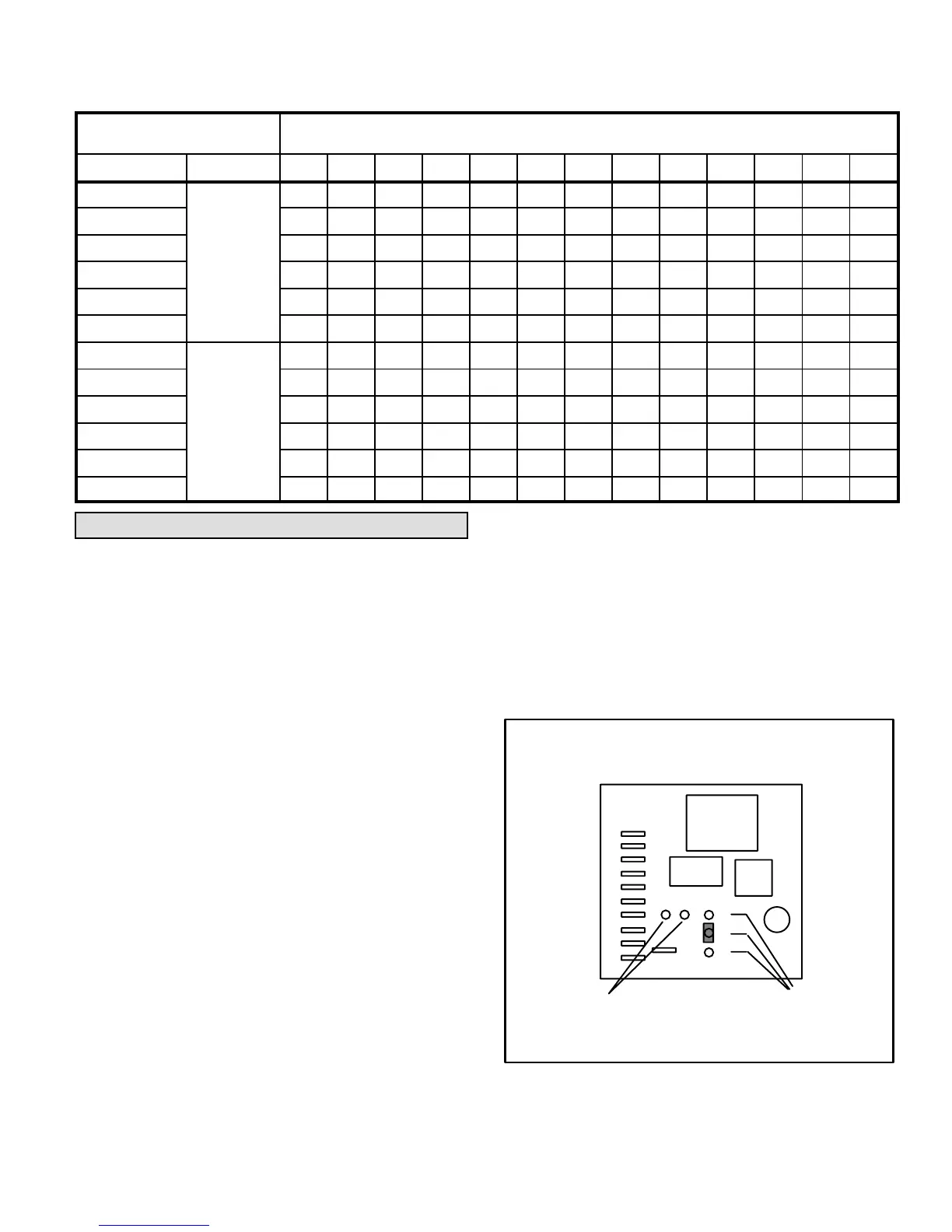
utes. See figure 9 for field adjustment of defrost timing.
The defrost control will initiate a defrost cycle if time period
has elapsed and the defrost sensor detects a temperature
below freezing. At the start of defrost cycle, the defrost con
trol will energize the reversing valve solenoid, shifting the
reversing valve and de−energizing the outdoor fan. The de
frost relay will also close energizing tempering heat for in
creased comfort during defrost , if the unit is so equipped.
The unit will remain in the defrost mode until the defrost
sensor has determined that the frost has been removed
from the coil or a 10 minute time period has elapsed.
T1T2T3
DEFROST
TEST PINS
DEFROST TIME
PINS
(T1, T2, T3)
JUMPER SHOWN ON T2 PIN
DEFROST CONTROL TEST AND
TIME PIN LOCATIONS
T1 = 30 MINUTES
T2 = 60 MINUTES
T3 = 90 MINUTES
FIGURE 9
The defrost control is also equipped with a set of test pins to
aid in troubleshooting of the defrost system. The following
is a brief outline of the testing of the defrost system.
 Loading...