Page 3
I − UNIT COMPONENTS
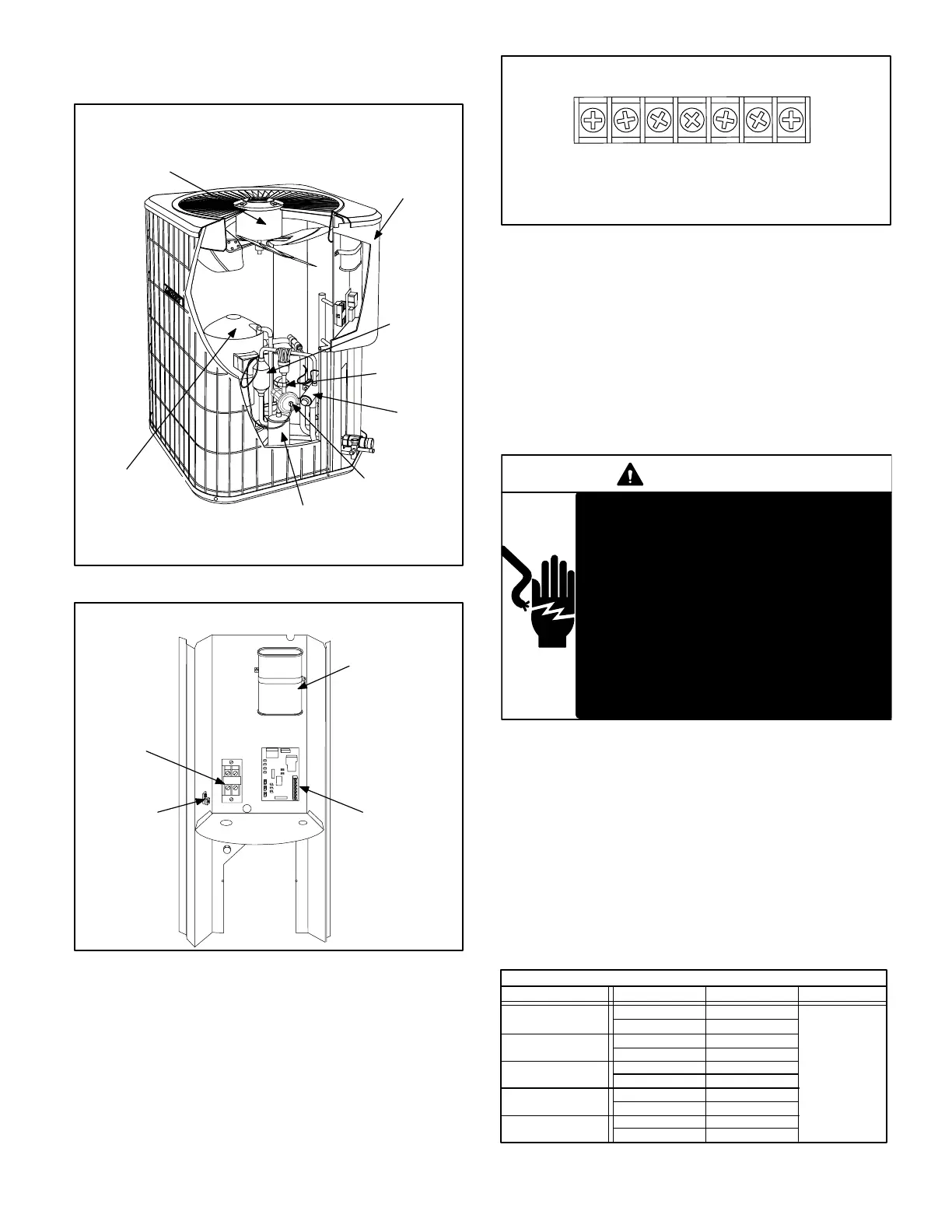
Unit components are illustrated in figure 1.
COMPRESSOR
CHECK/EXPANSION
VALVE
CONTROL
BOX
REVERSING
VALVE
SUCTION
MUFFLER
OUTDOOR
FAN/MOTOR
12HPB UNIT COMPONENTS
FIGURE 1
DEFROST
THERMOSTAT
BI-FLOW
FILTER DRIER
FIGURE 2
DUAL CAPACITOR
(C12)
COMPRESSOR
CONTACTOR
(K1)
12HPB UNIT CONTROL BOX
GROUNDING
LUG
DEFROST
CONTROL
(CMC1)
A − Control Box (Figure 2)
12HPB units are not equipped with a 24V transformer. All
24 VAC controls are powered by the indoor unit. Refer to
wiring diagram.
Electrical openings are provided under the control box cov-
er. Field thermostat wiring is made to a 24V terminal strip
located on the defrost control board located in the control
box. See figure 3.
CRW1OY1TL
T" & L" connections are used only if ambient
thermistor and service light are installed in the
12HPB and the proper room thermostat is used.
Only early model units will have this feature.
24V THERMOSTAT TERMINAL STRIP
FIGURE 3
1 − Compressor Contactor K1
The compressor is energized by a contactor located in the
control box. See figure 2. Single−pole and two-pole con-
tactors are used in 12HPB series units. See wiring dia-
grams for specific unit. K1 is energized through the con-
trol board by the indoor thermostat terminal Y1 (24V)
when thermostat demand is present.
DANGER
Electric Shock Hazard.
May cause injury or death.
Disconnect all remote electrical power
supplies berore opening unit panel. Unit
may have multiple power supplies.
Some units are equipped with single−
pole contactors. When unit is equipped
with a single−pole contactor, line voltage
is present at all components (even when
unit is not in operation).
2 − Dual Capacitor C12
The compressor and fan in 12HPB series units use perma-
nent split capacitor motors. The capacitor is located inside the
unit control box (see figure 2). A single dual" capacitor (C12)
is used for both the fan motor and the compressor (see unit
wiring diagram). The fan side and the compressor side of the
capacitor have different MFD ratings. See table 1 for dual ca-
pacitor ratings.
TABLE 1
Unit MFD VAC
12HPB (C12) DUAL CAPACITOR RATING
12HPB24
12HPB30
12HPB48
5
40
5
45
7.5
370
7.5
60
80
Terminal
FAN
HERM
FAN
HERM
FAN
HERM
FAN
HERM
12HPB60
12HPB36/42
5
50
FAN
HERM
 Loading...


