Page 4
3 − Defrost System
12HPB units built prior to April 2002
The 12HPB defrost system includes two components: a
defrost thermostat, and a defrost control.
a − Defrost Thermostat
The defrost thermostat is mounted on the liquid line be-
tween the check/expansion valve and the distributor. When
defrost thermostat senses 35_F (2_C) or cooler, its contacts
close and send a signal to the defrost control board to start the
defrost timing. It also terminates defrost when the liquid line
warms up to 70_F (21_C).
b − Defrost Control
The defrost control board in the 12HPB series units has the
combined functions of a time/temperature defrost control, de-
frost relay, time delay, diagnostic LEDs and field connection
terminal strip.
The control provides automatic switching from normal heating
operation to defrost mode and back. During compressor cycle
(room thermostat demand cycle), if the O" input is not on and
the defrost thermostat is closed, the control accumulates com-
pressor run times at 30, 60, or 90 minute field adjustable inter-
vals. When the accumulated compressor run time ends, the
defrost relays are energized and defrost begins.
Defrost Control Timing Pins
Each timing pin selection provides a different accumulated
compressor run period during one thermostat run cycle.
The defrost interval can be adjusted to 30, 60 or 90 minutes.
See figure 4. The defrost period is a maximum of 14 minutes
and cannot be adjusted. If no timing is selected, the control de-
faults to 90 minutes.
A TEST option is provided for troubleshooting. When the
jumper is placed across the TEST pins, the timing of all
functions is reduced by a factor of 128. For example, a 30
minute interval during TEST is 14 seconds and the 14 min-
ute defrost is reduced to 6.5 seconds.
The TEST mode may be started at anytime. If the jumper is in
the TEST position at power−up or for longer than five minutes,
the control will ignore the TEST selection and will default to a
90 minute interval.
Time−Delay
12HPB model units built prior to August 1996 will fea-
ture a time off delay. The timed−off delay is five minutes
long. Without the time delay it would be possible to
short cycle the compressor. A scroll compressor, when
short cycled, can run backward if head pressure is still
high. It does not harm a scroll compressor to run back-
ward, but it could cause a nuisance tripout of safety lim-
its (internal overload). For this reason, if a TOC delay
should fail, it must be replaced. Do not bypass the con-
trol. Later model compressors have an arrest feature
which eliminates the need for the TOC. This feature is
internally built and mechanically prevents the compres-
sor from turning backwards.
Pressure Switch Safety Circuit
The defrost control incorporates a pressure switch safety
circuit that allows the application of up to two optional pres-
sure switches; high pressure and/or loss of charge. See
figure 4. During a demand cycle, the defrost control will
lock out the unit on the third instance the unit goes off on
any pressure switch wired to this circuit. The diagnostic LEDs
will display a pattern for a lockout pressure switch on the third
open pressure switch occurrence. See table 2. The unit will re-
main locked out until 24 volt power is broken to terminal R" on
the defrost board and then remade.
Remove factory−installed jumper before connecting op-
tional pressure switches to control board. When two pres-
sure switches are used, wire each switch to one set of ter-
minals PS1 and PS2 on the defrost control board. See fig-
ure 4. When only one pressure switch is used, wire the
switch to the two outside terminals of the pressure switch
connections.
NOTE: If not using a pressure switch, the factory−installed
jumper wire must be connected, or unit will not operate.
Ambient Thermistor & Service LightConnection
12HPB model units built prior to August 1996 will have a de-
frost control board which provides terminal connections for a
monitoring kit (part number 76F53) which includes an ambient
thermistor and a service light. The monitor kit provides a ser-
vice light thermostat which activates the room thermostat ser-
vice light during periods of inefficient operation. The thermistor
compensates for changes in ambient temperatures which
might cause excessive thermostat droop. Later 12HPB model
units do not have the terminal connections; however the mon-
itoring kit can still be used. See Installation Instructions for
proper wiring.
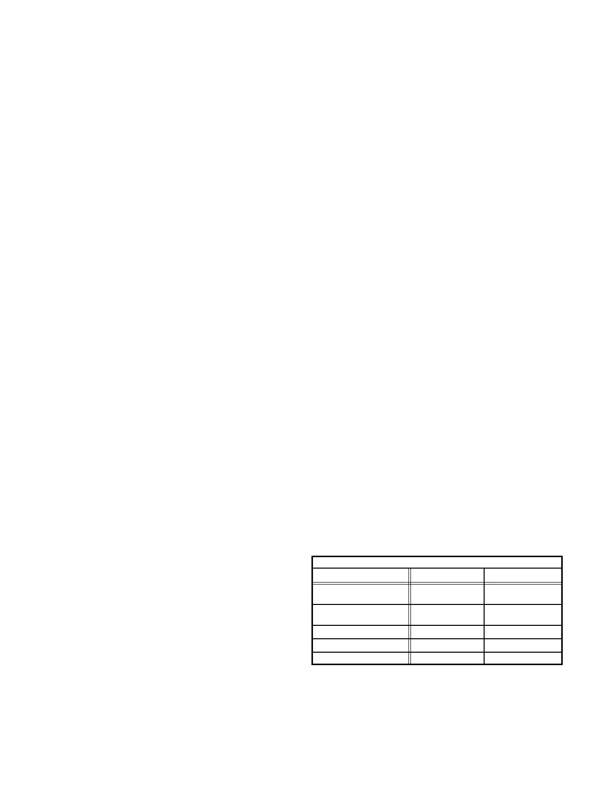
Diagnostic LEDs
The defrost board uses two LEDs for diagnostics. The
LEDs flash a specific sequence according to the condi-
tion.
TABLE 2
DEFROST CONTROL BOARD DIAGNOSTIC LED
MODE LED 1 LED 2
Normal Operation/
Power to board
Flash together with
LED 2
Flash together with
LED 1
Time Delay
To Protect Compressor
Alternating Flashes
with LED 2
Alternating Flashes
with LED 1
Pressure Switch Open Off On
Pressure Switch Lockout On Off
Board Malfunction On On
 Loading...


