Page 8
FAN
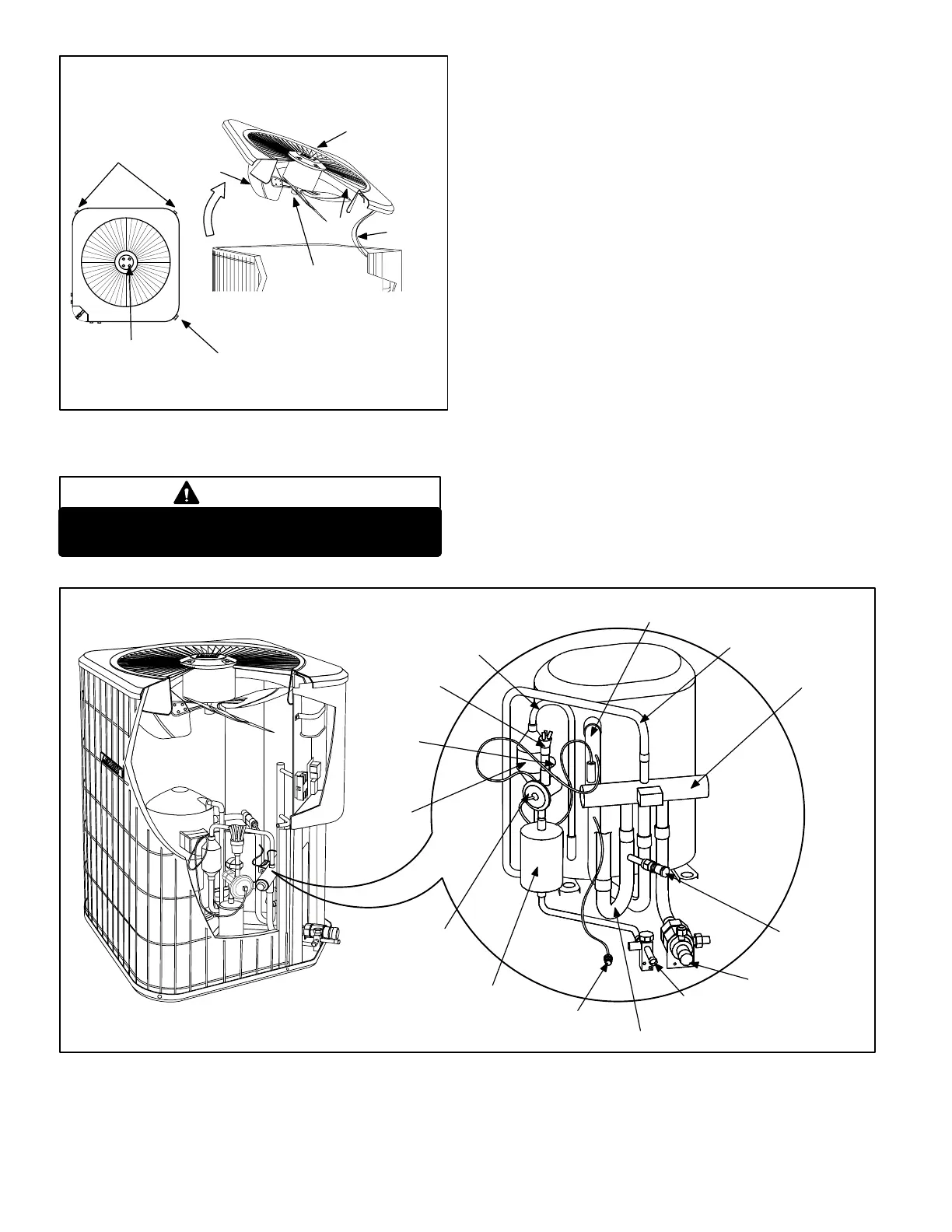
CONDENSER FAN MOTOR
AND COMPRESSOR ACCESS
Remove (7) screws
REMOVE (7) SCREWS
SECURING FAN GUARD.
REMOVE FAN GUARD/FAN
ASSEMBLY.
FAN GUARD
WIRING
FIGURE 10
Remove (4) nuts
ALIGN FAN HUB
FLUSH WITH
MOTOR SHAFT
Make sure all power is disconnected before
beginning electrical service procedures.
DANGER
C − Outdoor Fan Motor
All units use single−phase PSC fan motors which require a run
capacitor. In all units, the condenser fan is controlled by
the compressor contactor.
ELECTRICAL DATA tables in this manual show specifi-
cations for condenser fans used in 12HPBs.
Access to the condenser fan motor on all units is gained
by removing the seven screws securing the fan assem-
bly. See figure 10. The condenser fan motor is removed
from the fan guard by removing the four nuts found on
the top panel. If condenser fan motor must be replaced,
align fan hub flush with motor shaft. Drip loops should
be used in wiring when servicing motor.
D − Reversing Valve L1 and Solenoid
A refrigerant reversing valve with electromechanical so-
lenoid is used to reverse refrigerant flow during unit op-
eration. The reversing valve requires no maintenance. It
is not repairable. If the reversing valve has failed, it must
be replaced.
If replacement is necessary, access reversing valve by re-
moving the outdoor fan motor. Refer to figure 10.
II − REFRIGERANT SYSTEM
See figure 11 for unit refrigerant components. Refer to figure
12 and 13 for refrigerant flow in the heating and cooling
modes. The reversing valve is energized during cooling
demand and during defrost.
VAPOR LINE
SERVICE
VALVE
MUFFLER
DISTRIBUTOR
FILTER/DRIER
(BI−FLOW)
REVERSING
VALVE
EXPANSION VALVE
FIGURE 11
12HPB REFRIGERATION COMPONENTS
LIQUID LINE
SERVICE VALVE
VAPOR LINE
PRESSURE TAP
FITTING
DEFROST
THERMOSTAT
PROCESS
COUPLING
SUCTION LINE
DISCHARGE
LINE
SUCTION LINE
CHECK AND
 Loading...


