Page 13
Charging
The 16HPX unit is factory-charged with enough HFC-
410A refrigerant to accommodate a 15-foot length of re-
frigerant piping. Charge should be checked and adjusted
using the tables provided on the charging procedure stick-
er on the unit access panel. Detailed information is given
in the 16HPX Installation and Service Procedures manual,
which is available on LennoxPros.com.
System Conguration
This section addresses:
• Unit components (sensors, temperature switch, pres-
sure switches and demand defrost control)
• Second-stage operation
UNIT COMPONENTS
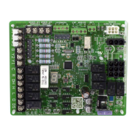
Demand Defrost Control (A108)
The demand defrost control measures dierential tem-
peratures to detect when the system is performing poorly
because of ice build-up on the outdoor coil. The control
self-calibrates when the defrost system starts and after
each system defrost cycle. The demand defrost control
components are shown in gure 15.
• Demand defrost control connections, jumpers and LED
locations are shown in gure 15.
• Demand defrost control connections, jumpers and LED
descriptions are listed on table 2.
• Demand defrost control status, fault and lockout LEDs
are listed in table 3.
24V TERMINAL STRIP
CONNECTIONS
(P2)
DIAGNOSTIC LEDS
(DS1 AND DS2)
PRESSURE
SWITCH CIRCUIT
CONNECTIONS
TEST PINS (P1)
Note - Component locations vary by board manufacturer.
SENSOR CONNECTION
(COIL AND AMBIENT
SENSORS)
(P4)
REVERSING VALVE
(O OUT)
DELAY PINS
(P5)
LOW AMBIENT
THERMOSTAT PINS
(P3)
DEFROST TERMINATION
PIN SETTINGS (P1)
Demand Defrost
Control (A108)
FIGURE 15
 Loading...