Page 19
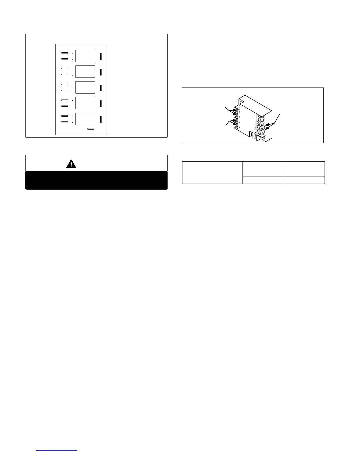
A11
COIL COIL COIL COIL COIL
GW1W2Y2Y1
K46 K77 K49 K67 K66
CC CCC
GND
NO NO NO NO NO NCNCNCNCNC
PILOT RELAY BOARD A11
BLOWER
PILOT
1st STAGE
HEATPILOT
2nd STAGE
HEAT PILOT
2nd STAGE
COOL PILOT
1st STAGE
COOL PILOT
FIGURE 12
WARNING
Do not remove or bypass the pilot relay board.
Control damage or failure could result.
19- Low Ambient Lockout Switch
(Compressor Monitor) S3 (all units)
CHA16 units are equipped with a single compressor moni
tor located in the unit control box. The compressor monitor
is a SPST bimetal thermostat which opens on a tempera
ture drop. It is connected inline with the 24VAC compres
sor control circuits. When outdoor temperature drops be
low 40°F the compressor monitor opens to electrically dis
connect all compressors. When the compressors are dis
connected, cooling demand is handled by optional
REMD16 economizer (if installed). The monitor automati
cally resets when outdoor temperature rises above 50°F.
NOTE-Compressor monitors must be disconnected if
optional low ambient kit is used.
20- Low Ambient Lockout Switch
(Compressor Monitor) S30
(1353, 1603 only)
CHA161353 and 1603 (10 and 12.5 ton) units are
equipped with a second compressor monitor (S30) used in
addition to compressor monitor S3. S3 is identical to S30.
In units equipped with two compressor monitors, S3 pro
tects the first stage compressors and S30 protects the
second stage compressors.
21-Compressor Motor Protector A9, A10
(2553, 2753, 3003 only)
Motor protectors A9 and A10 are used in all CHA16 18.5
ton and larger units to provide compressor overtempera
ture sensing which helps protect the compressors. Com
pressors in these units have thermistors imbedded in the
motor windings. The motor protectors monitor the sensors
in each compressor and shuts off the compressor when
resistance increases above a preset limit. As the compres
sor windings cool, the resistance through the sensors
drops and the control resets. Table 2 shows the resistance
values for the winding temperature sensors.
FIGURE 13
COMPRESSOR PROTECTOR A9, A10
TO
COMPRESSOR
SENSORS
24VAC POWER
IN SERIES WITH
CONTACTOR COIL
TABLE 2
Compressor Winding
Trip Ohms
Temp. Rise
Reset Ohms
Tem. Fall
Temperature Sensor
16K to 24K 5.5K to 6.9K
C-Cooling Components
Summary of Features
CHA16 series units use independent cooling circuits consist
ing of separate compressors, condenser coils and evapora
tor coils. See figures 14, 15, 16, 17 and 18. See figure 16 for
CHA161853 vapor circuitry and
figure 17 for CHA161853 liquid circuitry. A draw-through type
condenser fan is used in all units. CHA16823, 953 units use
a single fan. All other units use two. All units are equipped with
a single belt drive blower that draws air across the evaporator
during unit operation.
On all units cooling may also be supplemented by field
installed economizer. The evaporators are slab type and are
stacked as shown in figures 19, 20 and 21. Each evaporator
uses a thermostatic expansion valve as the primary expan
sion device. Each evaporator is also equipped with enhanced
fins and rifled tubing. CHA161853 units are equipped with
two condenser coils split into three independent circuits.
Compressor 1 uses an independent circuit in the right con
denser coil, compressor 2 uses an independent circuit in the
left condenser coil and compressor 3 uses an independent
circuit split between the left and right condenser coils. See fig
ures 17and 20. In all units each compressor is protected by a
crankcase heater, high pressure switch and loss of charge
switch. Additional protection is provided by factory installed
low ambient thermostat (unit control box) and freezestats (on
each evaporator). Each cooling circuit is equipped with a ther
mometer well for charging.