Page 79
A17 diagram
with B9 diagram
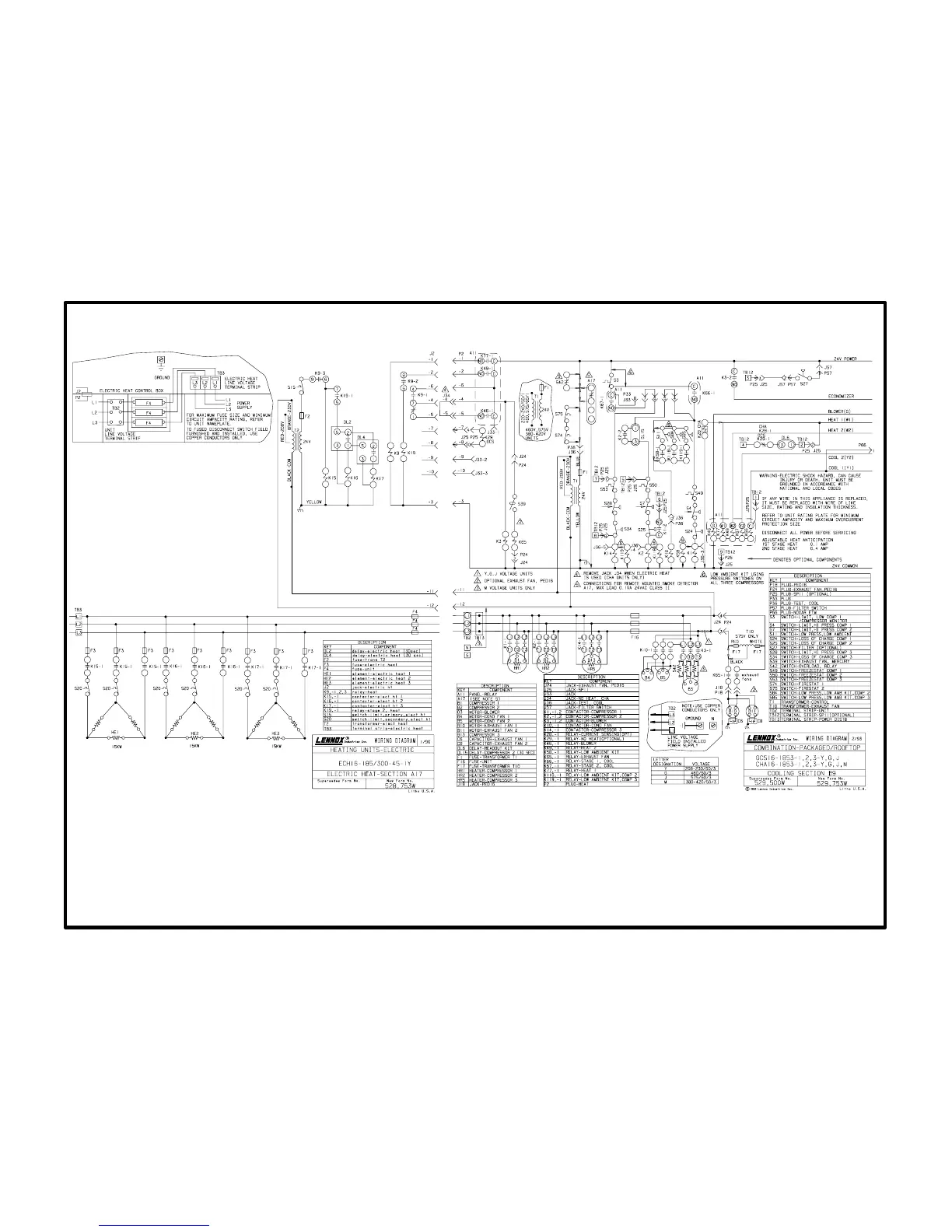
ECH16-185/255/275/300 45kW 208/230V Operating Sequence
Operation Sequence: A17 Section and B9 Sections
(45kW 208/230V electric heat wired to CHA16-1853)
1- 1st stage heating demand closes W1. W1 energizes pilot relay K77. K771 closes.
2- When K771 closes, heating pilot relay K9 is energized. K91 switches and K93 closes.
K92 closes to enable K19.
3- When K91 switches, indoor blower contactor K3 is energized (and optional power exhaust
fan relay K65 is enabled when K32 contacts close).
4- When K93 closes, electric heat contactor K15 is energized. K151 closes.
5- When K151 closes, heating elements HE1 are energized. All elements are arranged in a
Delta" configuration for 208/230V operation.
6- Additional heating demand W2 energizes pilot relay K49. K49-1 closes.
7- When K491 closes, pilot relay K19 is energized. K191 closes and DL2 is energized. After 30
seconds, DL2 closes.
8- When DL2 closes, contactor K16 and time delay DL4 are both energized. K161 closes and
DL4 begins counting.
9- When K161 closes, heating elements HE2 are energized.
10- When DL4 closes, contactor K17 is energized.
11- When K171 closes, heating element HE3 is energized.