Page 83
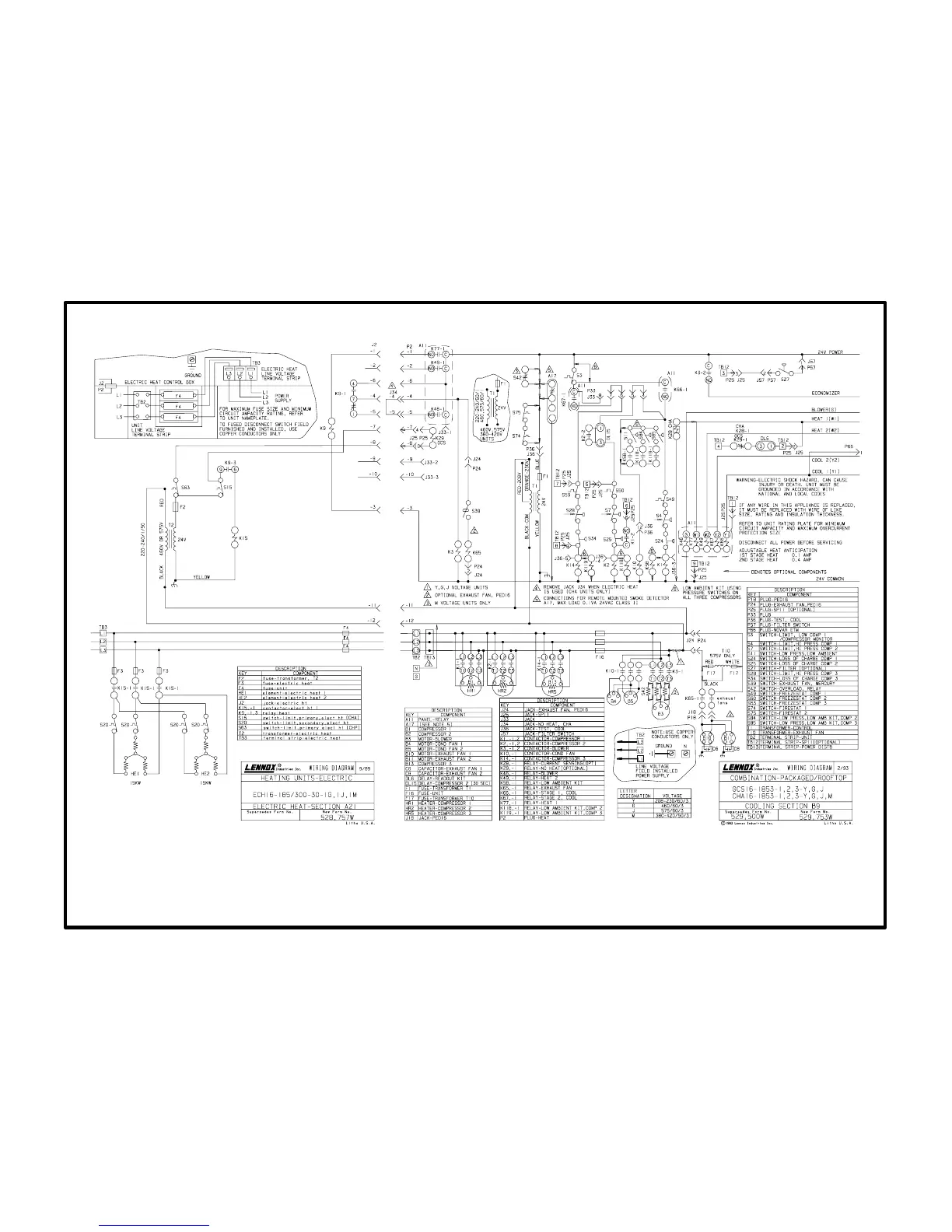
A21 diagram with B9 diagram
ECH16-185/255/275/300 30kW 460V & 575V Sequence
Operation Sequence: A21 Section and B9 Sections
(30kW 460V or 575V electric heat wired to CHA16-1853)
1- Noheat relay K29 is not used in this application and is omitted. Since this circuit remains
open, primary limit S63 remains unused.
2- 1st stage heating demand closes W1. W1 energizes pilot relay K77. K771 closes.
3- When K771 closes, heating pilot relay K9 is energized. K91 switches and K93 closes.
4- When K91 switches, indoor blower contactor K3 is energized (and optional power exhaust
fan relay K65 is enabled when K32 contacts close).
5- When K93 closes, electric heat contactor K15 is energized. K151 closes.
6- When K151 closes, heating elements HE1 and HE2 are both energized. The elements are
arranged in a Wye" configuration for 460V or 575V operation.
7- Additional heating demand W2 energizes pilot relay K49. K49-1 closes.
8- When K491 closes, nothing happens; ECH1618530G, J, M is a single stage electric
heater.