Page 25
When discharge pressure drops below 25+5 psig (indicat
ing a loss of charge in the system) the switch opens and
the compressor is de-energized. The switch automatically
resets when refrigerant is added and pressure in the dis
charge line rises above 55+
5 psig.
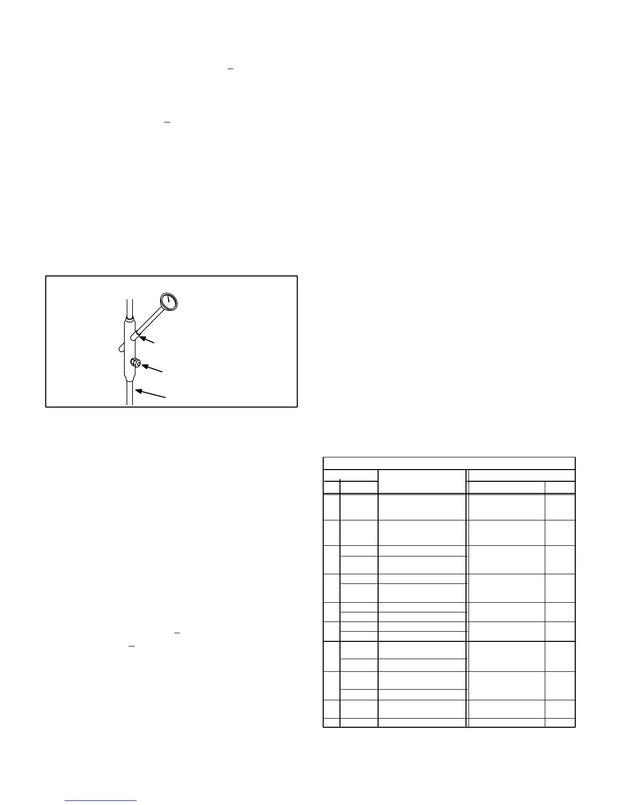
5-Thermometer Well (Figure 22)
All units are factory equipped with a thermometer well for
charging the unit. The well is used to accurately measure
the temperature of the liquid line. The temperature mea
sured is then used to calculate the approach or subcooling
temperature. Approach and subcooling temperatures are
compared to tables printed in the charging section of this
manual to determine the correct charge. Thermometer
wells are equipped with a gauge port for high pressure
gauge connection.
FIGURE 22
THERMOMETER WELL
THERMOMETER WELL
LIQUID LINE
GAUGE PORT
LIQUID LINE
To accurately measure the temperature of the liquid line,
the well should be filled with a light mineral oil before using.
This will ensure good heat transfer to the thermometer.
6-Freezestats S49, S50 and S53
Each evaporator is equipped with a low temperature limit lo
cated on a suction feeder. In three pump systems, S49 is lo
cated on the first stage compressor 1 coil, S50 is located on
the first stage compressor 2 coil and S53 is located on the
second stage coil. In two pump systems, S49 is located on
the first stage evaporator coil and S50 is located on the sec
ond stage evaporator coil.
Each freezestat is wired in series with its respective com
pressor contactor coil. Each freezestat is a SPST auto-re
set limit which opens at 29°F +
3°F on a temperature drop
and closes at 58°F + 4°F on a temperature rise. To prevent
coil icing, the freezestats open during compressor opera
tion to temporarily disable the respective compressor until
the coil warms sufficiently to melt any accumulated frost.
If the freezestats are tripping frequently due to coil icing,
check the unit charge, airflow and filters before allowing unit
back in operation. Make sure to eliminate all conditions
which might promote evaporator ice buildup.
7-Condenser Fans B4 and B5
The specifications tables on pages 2-6 in this manual
shows the specifications of condenser fans used in
CHA16 series units. Condenser outdoorfans in all
CHA16CHP16CHA16 units (all voltages) use three-phase
motors which do not require a run capacitor. CHA16823
and CHA16953 units are equipped with a single condens
er fan which operates during all compressor operation. All
other CHA16 units are equipped with two condenser fans.
In CHA161603 and CHA161853 units, both condenser
fans are energized upon receiving a first stage cooling de
mand. Condenser fans draw air across both condenser
coils during all compressor operation. In all other CHA16
series units, the condenser fans operate independently
and are staged with the compressors.
D-Blower Compartment/
Power MakeUp Components
1-Indoor Blower Motor B3
All CHA16 units use threephase singlespeed blower motors.
CFM adjustments are made by adjusting the motor pulley
(sheave). Blower motor ratings are shown in table 23. Motors
are equipped with sealed ball bearings. All motors and oper
ate at 1725 to 1760 RPM and all are internally overload pro
tected. Units may be equipped with motors manufactured by
Century, G.E., Emerson, Marathon or other manufacturer.
Electrical FLA and LRA specifications vary by manufacturer.
See unit rating plate for information specific to your unit.
Standard
TABLE 23
BLOWER MOTOR
Usage
Volts Phase
208/230
switchable to 460
3
3
HP
2
3
Electrical Characteristics
CHA16823Y,G
CHA16953-Y,G
CHA161353Y,G
Drive
Units
Standard
Optional
CHA16823J
CHA16953-J
CHA161353J
2 Standard 575
CHA161353Y,G
Standard
CHA161603Y,G
CHA161853Y,G
208/230
switchable to 460
3
3
Optional CHA161353J
Standard
CHA161603J
CHA161853J
3
575
5
Optional CHA161853Y,G
Standard CHA162553Y,G
208/230
switchable to 460
3
5
Optional CHA161853J
Standard CHA162553J
3575
7.5
Optional
CHA162553Y,G
CHA162753Y,G
CHA163003Y,G
208/230
switchable to 460
3
7.5
3575
Standard
Optional
CHA162553J
CHA162753J
CHA163003J
10 Optional CHA163003Y,G
208/230
switchable to 460
3
10 3575Optional CHA163003J