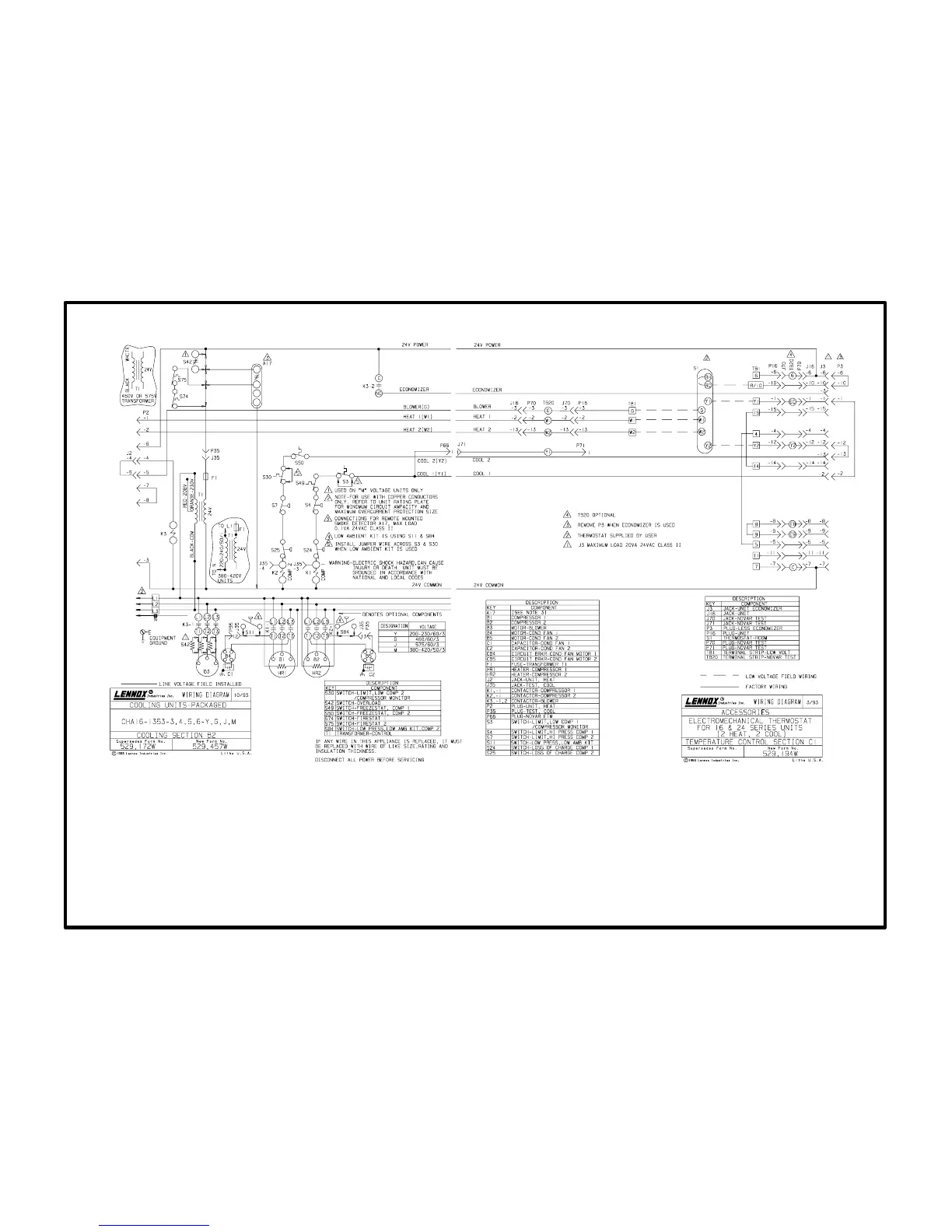
CHA161353 Operation Sequence: B2 Section and C1 Sections
(Basic Unit with Basic Electromechanical Thermostat)
Blower Operation:
1- Blower demand from thermostat terminal G energizes blower contactor K3.
2- N.O. K31 closes, blower begins operation. N.O. K32 closes energizing economizer damper motor
(if economizer is installed, outdoor damper drives to minimum position).
1st Stage Cooling (both compressors B1 and B2 operate separately):
3- Cooling demand energizes Y1 and G in the thermostat. G energizes blower (see step 1.)
4- 24VAC power is routed through compressor monitor S3, N.C. freezstat S49, N.C. high pressure
limit S4 and N.C. low pressure limit S24 to energize compressor contactor K1.
5- N.O. Contacts K1-1 close energizing compressor B1 and condenser fan B4.
2nd Stage Cooling:
6- Second stage cooling demand energizes Y2. 24VAC power is routed through freezestat S50, com
preesor monitor S3, high pressure limit S7 and low pressure limit S25 energizing compressor con
tactor K2.
7- N.O. contacts K21 close energizing compressor B2 and condenser fan B5.
1st Stage Heating: (See CHA161853 with Electric Heat Pages 5657)
8- Heating demand energizes W1 in the thermostat. The operation sequence of electric
heat units varies depending on size (kW input rating) and line voltage rating.
2nd Stage Heating (If equipped with multiple stage heating):
(See CHA161853 with Electric Heat Pages 5657)
9- Additional heating demand energizes W2 in the thermostat. The operation sequence of
electric heat units varies depending on size (kW input rating) and line voltage rating.
Safety Blower Operation:
10- If either limits in the electric heat section trip, the heating elements are immediately deen
ergized.
11- The indoor blower remains energized powered by K3 which is energized by thermostat de
mand.
Page 67
B2 diagram
with C1 diagram
CHA16-1353 Operating Sequence