Page 72
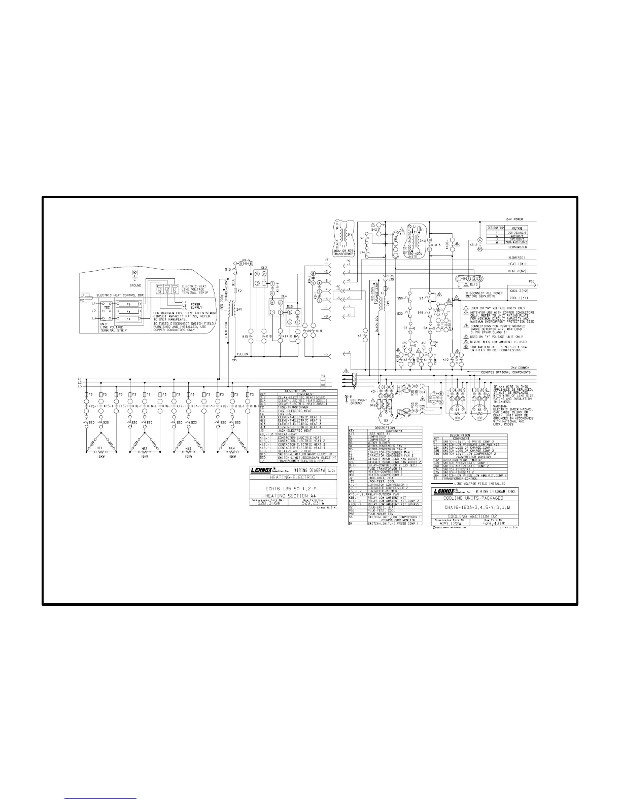
A4 diagram
with B2 diagram
ECH16-82/95/135/160 50kW 208/230V Operating Sequence
Operation Sequence: A4 Section and B2 Sections
(50kW 208/230V electric heat wired to CHA16-1603)
1- Control voltage in this heater is supplied by a separate transformer T2 which is powered at all
times.
2- 1st stage heating demand closes W1. W1 energizes relay K9.
3- When K91 switches, indoor blower contactor K3 is energized. The indoor blower is pow
ered (and optional economizer opens to minimum position when K32 contacts close).
When K92 closes, second stage heat is enabled. When K93 closes, control voltage
passes through primary limit S15 to energize contactor K15 and time delay DL2.
4- When K151 closes, heating elements HE1 are energized. All elements are arranged in a Del
ta" configuration for 208/230V operation.
5- DL2 closes 30 seconds later to energize contactor K16.
6- When K161 closes heating elements HE2 are energized.
7- Additional heating demand W2 passes through K92 to energize relay K19.
8- When K191 switches, time delay DL4 is energized. DL4 closes 30 seconds later to energize
contactor K17 and time delay DL5.
9- When K171 closes heating elements HE3 are energized,
10- DL5 closes after 30 seconds to energize contactor K18 is energized.
11- When K181 closes, heating elements HE4 are energized.