45
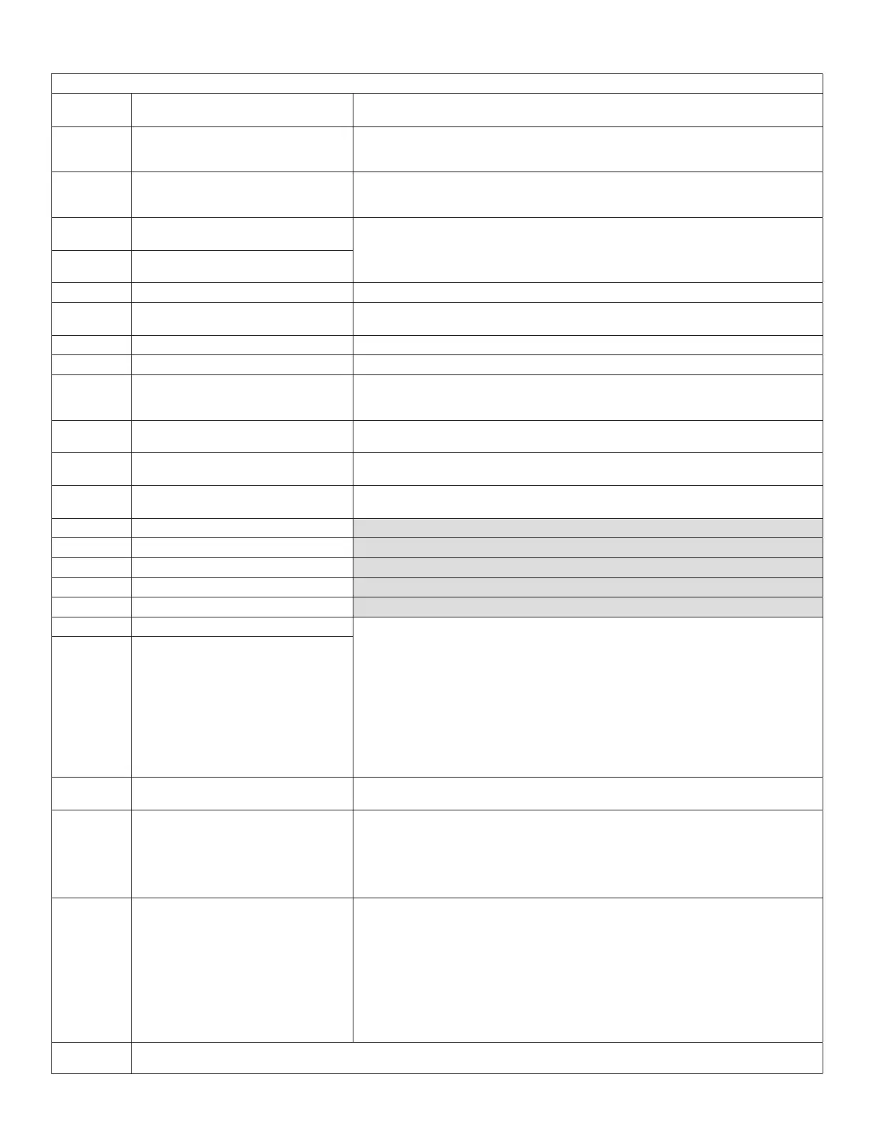
Table 11. CORE Control System Alarm and Event Codes
SELECTED ALARMS (MARKED WITH * IN TABLE RESULT IN THE CLOSURE OF THE SERVICE RELAY CONTACTS (DO1).
ALARM
CODE
DISPLAY MESSAGE EVENT ACTION
166
GAS CAB PRESSURE SW CLOSED
GV1
This alarm will occur when the combustion air pressure switch (S18) is detected as closed
immediately after the furnace demand relay is energized and before the combustion air
blower is energized. Gas valve 1.
167
GAS CAB PRESSURE SW CLOSED
GV2
This alarm will occur when the combustion air pressure switch (S45) is detected as closed
immediately after the furnace demand relay is energized and before the combustion air
blower is energized. Gas valve 2.
168*
COMBUSTION AIR SW NOT OPEN
LOCKOUT GV1
SystemlockedoutduetoS45switchclosedandaspecicnumberoccurrencesdetected
based on Parameter 72 (max cai no prf occ) setting during a single cycle.
169*
COMBUSTION AIR SW NOT OPEN
LOCKOUT GV2
170 PWR EXH UNCONFIGURED CongurationID1,position3issetasU(uncongured).
171 PWR EXH CONFIG ERROR
CongurationID1,position4issetcorrectly.ifposition3isconguredthenposition4
must be also.
172 EP UNCONFIGURED Economizer should be installed and blower should be ECM type.
173 AIR FLOW SW CONFIG ERR VerifythatCongurationID2,position1issetcorrectly.
174 BYPAS DAMPER CONFIG ERR
Room bypass damper operation is only compatible with cab blowers. Unit Controller will
onlyallowzonebypassunitoperationifcongurationID1issettoinstalledforunitswithB
orTtypeblowers.Alarmwillautomaticallyclearwhencongurationconictiscorrected.
175 NO INPUT SHARING
Alarm will occur if load shedding input is shared with other optional devices or inputs, for
example-global,bloweroverload,drainpanoverow,etc.
176 SBUS OBSOLETE M2 CMD
This alarm occurs when a SBUS master device sends a M2 style command to the CORE
Unit Controller. The alarm is immediately cleared and a history of the event is stored.
177 NO MODEL NUMBER
Missingmodelcongurationdata.Runsetup>installandcompletemodelnumber
information.
178 LOW SUMP SUPERHEAT
179 STRIKE3 LOW SUMP SUPERHEAT
180 DEFECTIVE CRANKCASE HEATER1
181 DEFECTIVE CRANKCASE HEATER2
182 SUCTION PRESSURE SENSOR
183 COMP1 SUMP TEMP SENSOR • Alarm will occur when an open or short condition is detected. Alarm will also occur
when unit controller via the temperature sensor detects an out of range. Valid range
is 30°F to 150°F. Possible causes are faulty temperature sensor / circuit or improper
installati
• The alarming value indicates which Compressor Sump Temp sensor failed.
NOTE: Not supported in Model L.
0 - Tandem 1 Compressor 2 Sump Temp Sensor Failure
1 - Tandem 2 Compressor 2 Sump Temp Sensor Failure
NOTE: Not supported in Model L.
184 COMP2 SUMP TEMP SENSOR
185 ULTRA
Generic alarm for ultra issues. The alarming value will have different values for different
issues.
186* BLOWER MOTOR FAULT
In systems with EBM blower, prodigy shall start monitoring the motor alarm output
(normally closed relay contact) ten seconds after blower command is sent. The CORE Unit
Controller will stop unit operation if fault conditions (relay contact open logic input high)
are detected.
NOTE: Motor alarm is wired to P259 7; shared with VFD alarm and ECM blower rpm inputs.
Alarm will clear when in range temperature is detected.
187 INVERTER MINOR
• Alarming Value = Inverter error code
• Possible alarming values for Prodigy Alarm 187 are:
> 12 - High Comp Current
> 13 - High Heat sink temperature
> 14 - High PFC input current
• If the alarm continues after outdoor conditions have moderated, check the fan,
charge and coil. Alarm 187 will automatically clear when minimum off time expires.
• Refer to trouble shooting guide in service manual for more information.
NOTE: The inverter will automatically slow the compressor speed due to any of the above conditions and the condition drops below the
time-based dependence of the system’s output on present and past inputs.