6
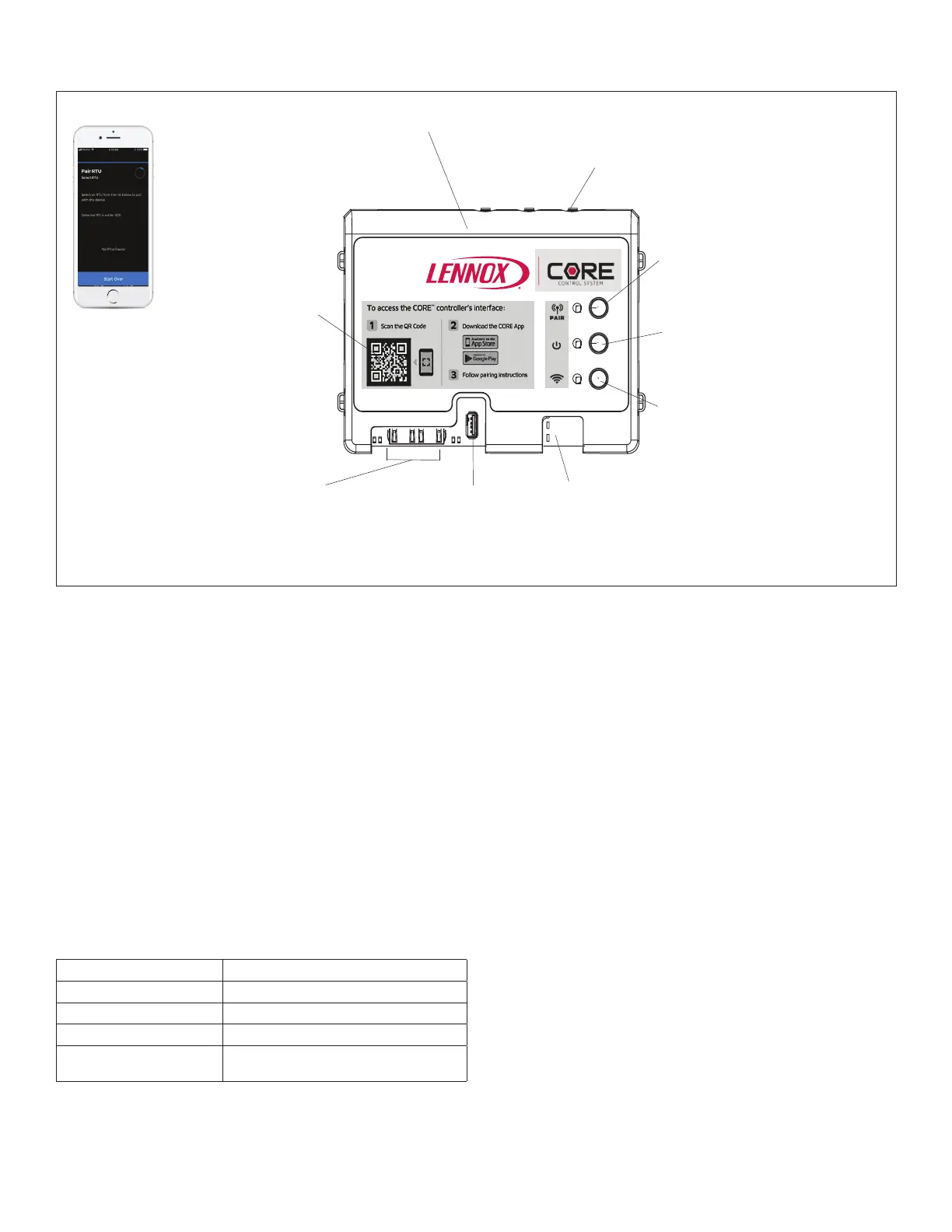
1.7. W4 Wireless Controller - Connections, Buttons and LEDs
Wireless Board (W4)
Service App QR Code
* Allow users to quickly nd the service app
2-Port IP Switch
BACnet IP
* Automatic rmware updates
* Allows daisy-chain connection
USB port
* Firmware Updates
* System Logs and Reports
* Conguration save/copy
Wireless Gateway Connector
* Connects to unit gateway (coax)
* Allows app and sensor connections
BACnet MS/TP
* Standard on all CORE Unit Controllers
* New objects supported
Pair Button and LED
* Pressing button allows
pairing to App.
* LED indicates pairing status - solid
blue indicates either BLE is booting up
or mobile device is already connected.
Green indicates ready for connection.
Blinking blue indicates in pairing mode.
Reset Button and Heart
Beat LED
* Reset Button for the W4 control
* Blinking LED indicates W4 power
Cloud / IP Button and LED
* Button not used at this time
* LED indicates BACnet and cloud
connectivity. Red LED indicates not
connected and green indicates connected.
Figure 3. W4 Controller Interfaces
1.8. Cloud Firmware Updates
• Internet connection is required
• On-demand or automatic
• CORE Unit Controller connects to cloud via IP (Ethernet)
• Can check on demand or nightly
> Congurableviaapp
> Default: On demand
• Free updates
• Updates are also available via USB
2. Network Types
The following are the types of communication network types
supported.
Table 3. Network Types
Screen Label Network Type
LON LonTalk
BACNET BACnet MS/TP and IP
LCONN L-Connection
RTU Rooftop Unit stand-alone mode status
indicator
3. Unit Operation
This section describes the display and control buttons, how
toconguretheunit,andhowtoreadstoredconguration
data, status, and alarms.
The CORE Unit Controller is an input and output junction
point. If in the thermostat mode, thermostat inputs at P297
result in an output to unit components. If the heartbeat LED
isnotashing,see”Table1.LEDOperationIndicators”on
page 5 for heartbeat operation. If the display shows
an alarm. If the thermostat input indicating lights are not
responding appropriately, check the thermostat or a DDC
control acting as thermostat inputs into P297.
Basic cooling and heating functions may be energized to test
major unit components by using the CORE Unit Controller
testing function or by using jumper wires on the Field Wiring
Termination plug P297.