5
Table 1. LED Operation Indicators
LED Status Indication Meaning
Heartbeat (HB)
(D33)
Green Slow Flash Normal Operation
Green Fast Flash Bootloader/rmwareupdatemode
No light Steady Off No voltage to M3 board or defective board
Green Steady On Unitinconguration/testmode(notinnormalmode)
S-BUS / PC
Connection (D70
and D71)
BUS (green)
Flickering
ON
Networktrafcpresent
TX (yellow)
Flickering
ON
Unit controller is transmitting
Thermostat Input Yellow
Indicates a
thermostat
demand
G - Blower on
W1 - First-Stage Heating
W2 - Second -Stage Heating
Y1 - First-Stage Cooling
Y2 - Second-Stage Cooling
OCP - Occupied
GLO - Global input
MODBUS Two LEDs that indicate transmit (TX) and receive (RX) activity.
Slow Flash = 1 second on; 1 second off.
Fast Flash = ½ second on; ½ second off.
A“ickering”LEDashessignicantlyfasterthana“fastash“.
NOTE: LEDs are energized by 24VAC thermostat inputs.
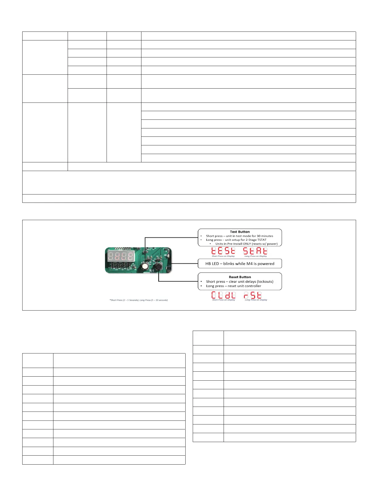
F. LOCAL INTERFACE - PUSH BUTTONS AND HEART BEAT
Figure 2. Push Buttons and Heart Beat
G. LOCAL INTERFACE - FOUR CHARACTER SEVEN
SEGMENT LED - STATUS CODES
Table 2. Status Codes
Status
Code
Denition
PnSt
Pre-Install
A173
Smoke
LoUt
Controller Lockout
Eror
Off On Alarm
d300
Delay up to 5 minutes
d020
Delay up to 20 seconds
dhUM
Dehumidication
ShEd
Compressor Load Shedding
Prht
Morning Warmup
Strt
Start up
FAh
Fresh Air Heating
Table 2. Status Codes
Status
Code
Denition
h050
Heating (50%)
PrCL
Pre-Cool
CEoP
Cool + Max Open Economizer
CE10
Cool + Modulate Economizer (10%)
FrCL
Free Cooling
FAC
Fresh Air Cooling
CO78
Cooling (78%)
671S
Blower On - (71.5%) OAS
623
Blower On (23%)
ioAS
No Demand - OAS
idLE
No Demand