IOM – FLEXY II – 1007 – E Page 62
- Check the 230V supply voltage of electronic board: the
phase on terminal 01 and the neutral conductor on
terminal 02
- Check the wiring of the signal 0-10V between terminal 64
(polarity 01 of the 24V) and terminal 66 (+ coming from the
actuator)
- Check the connection of the modulating solenoid valve
between the electronic board’s terminals 61 & 62
- Select the operating mode n°3
“output 0-330mA”:
Switch n°1 ON
Switch n°2 OFF
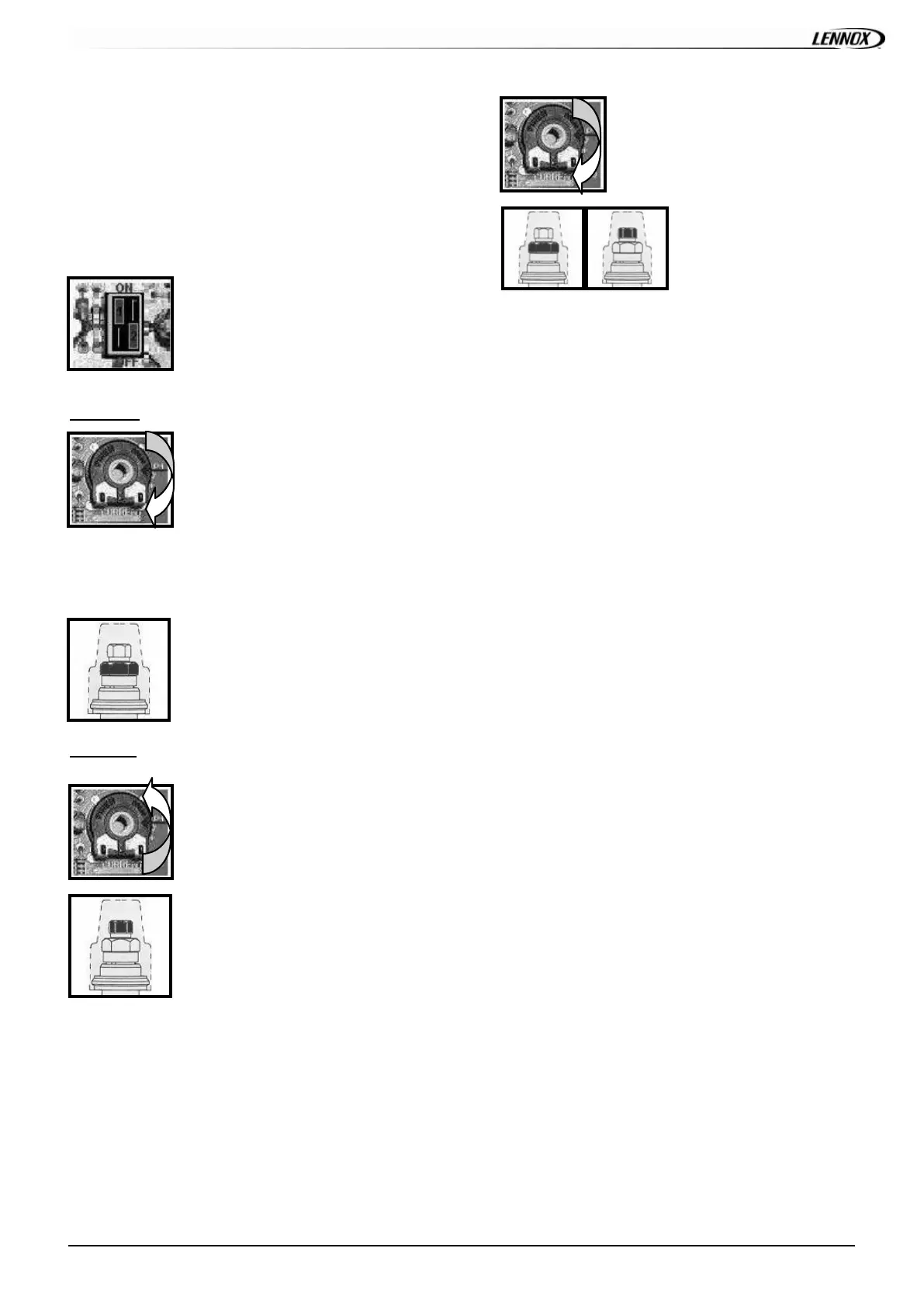
High heat:
- Place the potentiometer called
“current” on position Max.
- Apply 9V to the climatic output; the actuator and the gas
valve position themselves in full opening and the burner
starts.
- Regulate the value of the maximum
flow at 10.4mbar (for natural gas and at
approximately 1 3. 1 m b a r f or Groningen
gas) by operating on the adjusting nut
called “maximum pressure”.
Low heat:
- Place the potentiometer called
“current” on position Min
- Regulate the value of the minimum
flow at 2 mbar (for natural gas and at
approximately 2.6 mbar f or Groningen
gas) by operating on the adjusting nut
called “minimum pressure”.
- Bring back the potentiometer
towards the position + until obtaining
the desired 10.4mbar in high heat for
natural gas.
- Check the pressure
values for high and low
heat using the climatic
output and ref ine the
adjustments thanks to the nuts of the solenoid valv e.
- Check that by apply ing 10V to the climatic output, we do
not exceed the maximum pressure (10.4mbar f or natural
gas).
- Ditto, by disconnecting the
power supply of the solenoid valv e, check that the
pressure is the same one as the minimum pressure
regulated prev iously.
- Check the good reaction of the Honeywell board’s
regulation by apply ing 7V to its input; it must already
act on the position of the actuator and on the gas flow,
whic h m ust hav e a v alue lower t han t he max flow
ones.
: MODULATING GAS BURNER 60 & 120kW
 Loading...