3DJH
J-Gas Valve
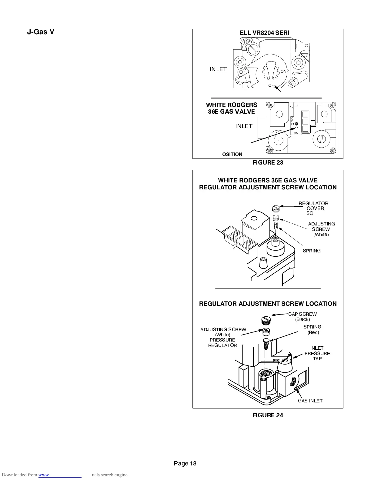
TheG23(X) usesa gas valvemanufacturedby Honeywell
or White Rodgers. See figure 23. The valve is internally
redundant to assure safety shut-off. If the gas valve must
be replaced, the same type valve must be used.
24VAC terminals and gas control knob are located on top of
the valve. All terminals on the gas valve are connected to
wires from the ignition control. 24V applied to the “PV” termi-
nals opens the pilot (-1 through -4 models) and 24V applied to
the “MV” terminals opens the valve on G23X. Inlet and outlet
pressure taps are located on the valve. A regulator adjust-
ment screw (figure 24) is located on the valve.
An LPG changeover kit is available from Lennox. The kit in-
cludes main and pilot burner orifices, burner corbel plate (Nox
only), and regulator conversion kit.
K-Combustion Air Blower Prove
(Pressure) Switch (S64)
G23(X) series units are equipped with a combustion air
(pressure) switch located on the vestibule panel. The switch
is connected tothe combustion air blower housing by means
of a flexible silicon hose. It monitors air pressure in the com-
bustion air blower housing. The other side of the pressure
switch is open to atmosphere.
The switch is a single-pole single-throw pressure switch
electrically connected in series with the ignition control. The
purpose of the switch is to prevent burner operation if the
combustion air blower is not operating.
On start-up, the switch senses that the combustion air blow-
er is operating. It closes a circuit to the ignition control when
pressure inside the combustion air blower increases above
the setpoint. The setpoint is measured in negative inches
water gauge. The pressure sensed by the switch is relative
to atmospheric pressure. If the flue becomes obstructed dur-
ing operation, the switch senses a loss of negative pressure
(drops below setpoint) and opens the circuit to the ignition
control.
The switch setpoint varies with unit model number. Look
for the setpoint printed on the side of the switch.
The switch is factory set and is not field adjustable. It is a
safety shut-down control in the furnace and must not be
bypassed for any reason.
FIGURE 23
21
2))
HONEYWELL VR8204 SERIES GAS VALVE
GAS VALVE SHOWN IN OFF POSITION
WHITE RODGERS
36E GAS VA
LVE
GAS VALVE
SHOWN
IN OFF
POSITION
INLET
INLET
FIGURE 24
,1/(7
35(6685(
7$3
&$3 6&5(:
%ODFN
$'-867,1* 6&5(:
:KLWH
635,1*
5HG
*$6 ,1/(7
35(6685(
5(*8/$725
REGULATOR
COVER
SCREW
$'-867,1*
6&5(:
:KLWH
635,1*
HONEYWELL VR8204 GAS VALVE
REGULATOR ADJUSTMENT SCREW LOCATION
WHITE RODGERS 36E GAS VALVE
REGULATOR ADJUSTMENT SCREW LOCATION
 Loading...