Page 31
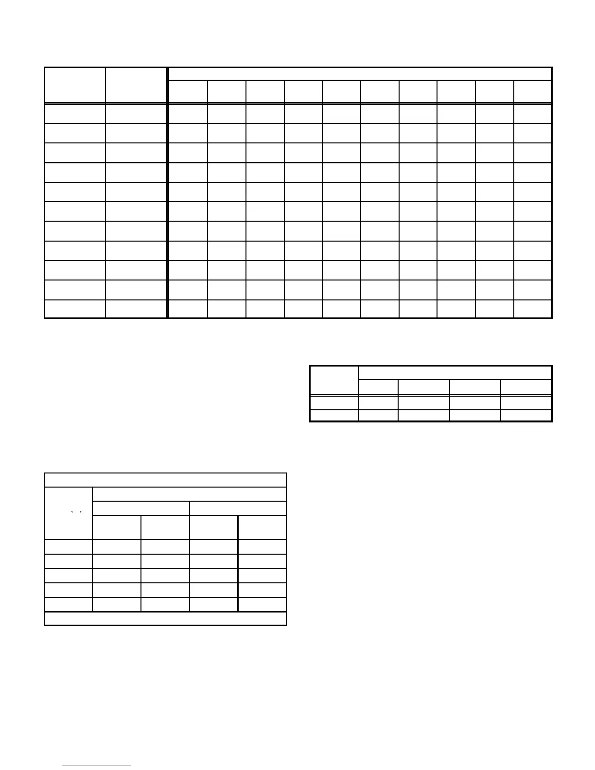
TABLE 16
GAS PIPE CAPACITY - FT
3
/HR (kL/HR)
Length of Pipe-Feet(m)
Iron Pipe Size
-Inches(mm)
Diameter
-Inches(mm)
10
(3.048)
20
(6.096)
30
(9.144)
40
(12.192)
50
(15.240)
60
(18.288)
70
(21.336)
80
(24.384)
90
(27.432)
100
(30.480)
1/4
(6.35)
.364
(9.246)
43
(1.13)
29
(.82)
24
(.68)
20
(.57)
18
(.51)
16
(.45)
15
(.42)
14
(.40)
13
(.37)
12
(.34)
3/8
(9.53)
.493
(12.522)
95
(2.69)
65
(1.84)
52
(1.47)
45
(1.27)
40
(1.13)
36
(1.02)
33
(.73)
31
(.88)
29
(.82)
27
(.76)
1/2
(12.7)
.622
(17.799)
175
(4.96)
120
(3.40)
97
(2.75)
82
(2.32)
73
(2.07)
66
(1.87)
61
(1.73)
57
(1.61)
53
(1.50)
50
(1.42)
3/4
(19.05)
.824
(20.930)
360
(10.19)
250
(7.08)
200
(5.66)
170
(4.81)
151
(4.28)
138
(3.91)
125
(3.54)
118
(3.34)
110
(3.11)
103
(2.92)
1
(25.4)
1.049
(26.645)
680
919.25)
465
(13.17)
375
(10.62)
320
(9.06)
285
(8.07)
260
(7.36)
240
(6.80)
220
(6.23)
205
(5.80)
195
(5.52)
1-1/4
(31.75)
1.380
(35.052)
1400
(39.64)
950
(26.90)
770
(21.80)
660
(18.69)
580
(16.42)
530
(15.01)
490
(13.87)
460
(13.03)
430
(12.18)
400
(11.33)
1-1/2
(38.1)
1.610
(40.894)
2100
(59.46)
460
(41.34)
1180
(33.41)
990
(28.03)
900
(25.48)
810
(22.94)
750
(21.24)
690
(19.54)
650
(18.41)
620
(17.56)
2
(50.8)
2.067
(52.502)
3950
(111.85)
2750
(77.87)
2200
(62.30)
1900
(53.80)
1680
(47.57)
1520
(43.04)
1400
(39.64)
1300
(36.81)
1220
(34.55)
1150
(32.56)
2-1/2
(63.5)
2.469
(67.713)
6300
(178.39)
4350
(123.17)
3520
(99.67)
3000
(84.95
2650
(75.04)
2400
(67.96)
2250
(63.71)
2050
(58.05)
1950
(55.22)
1850
(52.38)
3
(76.2)
3.068
(77.927)
11000
(311.48)
7700
(218.03)
6250
(176.98)
5300
(150.07)
4750
(134.50)
4300
(121.76)
3900
(110.43)
3700
(104.77)
3450
(97.69)
3250
(92.03)
4
(101.6)
4.026
(102.260)
23000
(651.27)
15800
(447.39)
12800
(362.44)
10900
(308.64)
9700
(274.67)
8800
(249.18)
8100
(229.36)
7500
(212.37)
7200
(203.88)
6700
(189.72)
NOTE-Capacity given in cubic feet of gas per hour (kilo liters of gas per hour) and based on 0.60 specific gravity gas.
F- Proper Gas Flow (Approximate)
Furnace should operate at least 5 minutes before check-
ing gas flow. Determine time in seconds for two revolu-
tions of gas through the meter. (Two revolutions assures
a more accurate time.) Divide by two and compare to time
in table 17 below. Adjust manifold pressure on gas valve
to match time needed.
NOTE- To obtain accurate reading, shut off all other
gas appliances connected to meter.
TABLE 17
GAS METER CLOCKING CHART
Seconds for One Revolution
G23(X)
Natural LP
Unit
1 cu ft
Dial
2 cu ft
Dial
1 cu ft
Dial
2 cu ft
DIAL
-50 72 144 180 360
-75 48 96 120 240
-100 36 72 90 180
-125 29 58 72 144
-150 24 48 60 120
Natural-1000 btu/cu ft LP-2500 btu/cu ft
G-High Altitude Derate
Pressure regulator may need to be adjusted, depending
on altitude. See table 18 for proper pressure regulator set-
ting.
TABLE 18
Manifold Absolute Pressure (Outlet) in. w.c.
ALTITUDE
0 - 4500 4501 - 5500 5501 - 6500 6501 - 7500
NAT. GAS 3.5 3.3 3.1 3.0
L.P. GAS 10.0 10.0 10.0 10.0
A natural to LP/propane gas changeover kit is required to
convert unit. Refer to the installation instructions supplied
with the changeover kit for conversion procedure.
The pressure switch is factory set. No adjustment is nec-
essary. The G23-50/75 units use the factory pressure
switch from 0 to 7500 feet. G23-100/125 and G23-150
units require a high altitude pressure switch for units
installed above 5000 feet. Order Lennox part number
97J50 for G23-100/125 and 18J35 for G23-150.
H-Flame Signal
A microamp DC meter is needed to check the flame signal
on the ignition control.
Flame (microamp) signalis an electricalcurrent which passes
from the furnace control through the sensor during unitopera-
tion. Current passes from the sensor through the flame to
ground to complete a safety circuit.
 Loading...