3DJH
TABLE 21
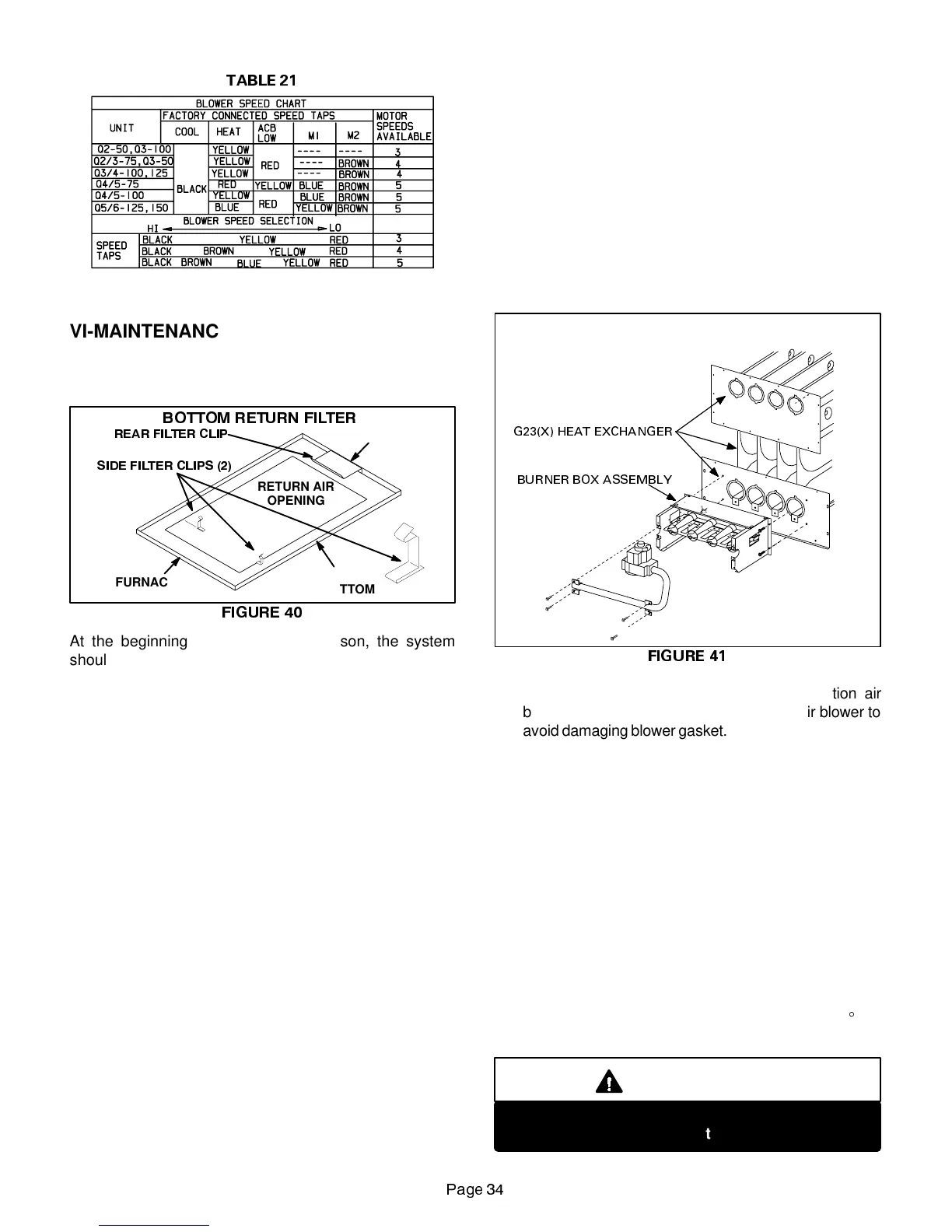
VI-MAINTENANCE
A-Filters
Retainers for optional return air filter are shown in figure
40.
),*85(
%27720 5(7851 ),/7(5
FURNACE
BASE BOTTOM
5($5 ),/7(5 &/,3
RETURN AIR
OPENING
6,'( ),/7(5 &/,36
FURNACE
FRONT
FURNACE
BACK
At the beginning of each heating season, the system
should be checked as follows:
1. Filters should be inspected monthly and must be
cleaned or replaced when dirty to assure proper fur-
nace operation.
2. Optional foam filters available for the G23(X) can be
washed with water andmild detergent. Whendry, they
should be sprayed with filter handicoater prior to rein-
stallation. Filter handicoater is RP Products coating
no. 418 and is available as Lennox part no. P-8-5069.
3. If replacement is necessary, order Lennox part no.
31J8101 for 14 X 25 inch filter for G23(X)-50, and 75
units, P-8-7822 for 16 X 25 inch filter for Q3(X)-100
units, and P-8-7831 for 20” x 25 ” filters used on
Q3/4(X)-100, Q3/4(X)-125, Q4/5(X)-75, Q4/5(X)-100,
Q5/6(X)-125 and Q5/6(X)-150 units.
B-Cleaning Heat Exchanger and Burners
NOTE-Use papers or protective covering in front of fur-
nace while cleaning furnace.
Cleaning the heat exchanger requires a steel spring
“snake,” a reversible drill and a vacuum cleaner. The steel
springsnake may beconstructed by purchasinga4 ft. long
by 1/4” diameter steel wire cable and a 1/4” diameter wire
brush. These items are available at a hardware store. In-
sert wire endof brushinto theopen endof the springcable.
Crimp the cable around the brush so that the brush is se-
cured and will not comeoff duringcleaning. Attachthe oth-
er end of the cable to the reversible drill to complete the
tool for cleaning the heat exchanger. See figure 3 for parts
arrangement when disassembling furnace.
1 - Turn off both electrical and gas power supplies to fur-
nace.
2 - Remove flue pipe and top cap from unit. Mark anddis-
connect wiring from pressure switch and ignition con-
trol (-1 through -4 model units). Remove ignition con-
trol and pressure switch from upper vestibule panel.
3 - Remove uppervestibule panel to expose the combus-
tion air blower.
FIGURE 41
G23(X) BURNER AND
HEAT EXCHANGER REMOVAL
G23(X) HEAT EXCHANGER
BURNER BOX ASSEMBLY
4 - Remove three screws securing the combustion air
blower. Carefully remove the combustion air blower to
avoid damaging blower gasket. If gasket is damaged, it
must be replaced to prevent leakage.
5 - Remove collector box located behind combustion air
blower. Caremust be taken to avoiddamagingthe col-
lector box gasket. If the gasket is damaged it must be
replaced to prevent leakage.
6 - Mark then disconnect wires from gas valve and rollout
switch.
7 - Disconnect gas supply piping. Remove four screws
securing the burner manifold assembly to the lower
vestibule panel and remove the assembly from the
unit.
8 - For NOx units only, remove the screws holding the
flame baffles in the heat exchanger clam shells. Care-
fully remove each baffle from each heat exchanger
section. To avoid damaging baffles, turn baffles 90
E
be-
fore pulling out through heat exchanger outlet.
IMPORTANT
Mark each baffle so that they are returned to the
proper heat exchanger section.
 Loading...