Page 96
System Status Screen
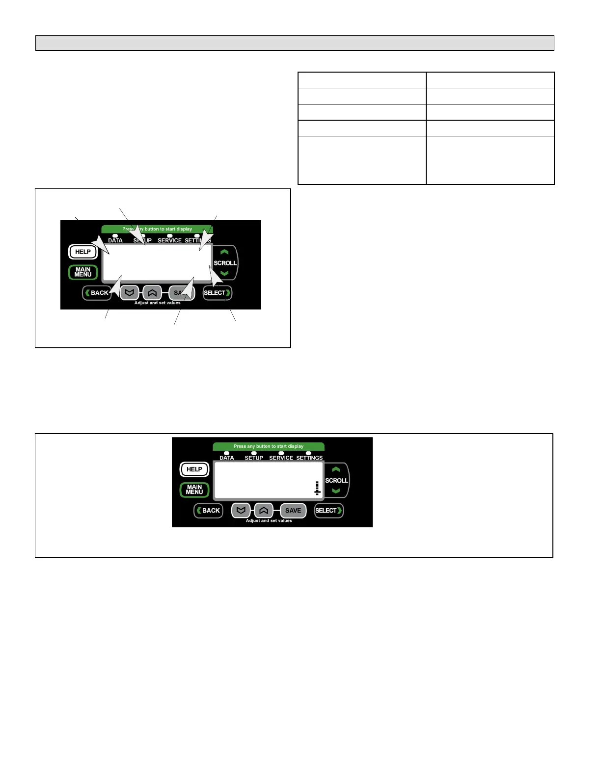
System Status Screen
The display shows operating mode if in normal operation.
Alarms will interrupt the display.
Alarm messages will appear on the display and remain there
until dismissed. Dismissing an alarms is just clearing the
alarm from using the entire screen to display the condition(s).
The alarm condition still exist and up to two alarm codes are
displayed along the right side of the screen above the
thermostat demand type status. To dismiss an alarm, press
the BACK button.
COOLING
UNOCC
RAT: 76.0F
DAT: 57.0F
ZONE AND DISCHARGE
AIR TEMPERATURES
OCCUPIED (OCC) OR
UNOCCUPIED (UNOCC)
FIRST TWO ALARMS THAT
ARE ACTIVE
NORMAL MODE
MESSAGE
Y1
THERMOSTAT
DEMAND TYPE
74, 93
LON ON
NETWORK
STATUS
Figure 32. System Status Display
Network Status
The second line on the left side (see figure 32) is used for
displaying network status. The status will indicate either ON
or OFF for the network employed. Network types are listed
in table 61.
Table 61. Network Status
Screen Label Network Type
LON LonTalk
BACNET BACnet
LCONN L-Connection
RTU Rooftop Unit (this is not a
networking status, but indic
ates if the RTU is ON or
OFF.
Unit Operation
This section describes the display and control buttons, how
to configure the unit, and how to read stored configuration
data, status, and alarms.
The M3 unit controller is an input and output junction point.
If in the thermostat mode, thermostat inputs at P297 result
in an output to unit components (see table 67 on page 146).
If the heartbeat LED is not flashing, see table 63 on page
97 for heartbeat operation. If the display shows an alarm,
refer to table 66 on page 137 for more information. If the
thermostat input indicating lights are not responding
appropriately, check the thermostat or a DDC control
acting as thermostat inputs into P297.
Basic cooling and heating functions may be energized to test
major unit components by using the M3 unit controller testing
function or by using jumper wires on the Field Wiring
Termination plug P297.
Alarm Status Display
Figure 33 shows how alarms are displayed. Alarming value
may indicate the condition which triggered the alarm
(temperature, voltage, pressure, time, etc.).
ALARM 173
2.4.2014 12: 02: 24
ALARMING VALUE = 0
AIR FLOW SWITCH CON
ALARM(S) ARE PRESENT -
ALARM CODE, ALARMING
VALUE, AND DATE TIME STAMP
(HOUR, MINUTE AND SECONDS)
OF ALARM EVENT.
COMPLETE ALARM LISTING AND
DESCRIPITIONS ARE AVAILABLE BY
SCROLLING DOWN (A DOWN AR
ROW ON THE SCREEN INDICATES
MORE TEXT FOLLOWS)
WHILE THE ALARM IS SHOWING ON THE STATUS SCREEN, PRESS THE
HELP BUTTON FOR FURTHER DETAILS CONCERNING THE ALARM.
Figure 33. Alarm Code Readout Example