CDU Operating & Maintenance Guide Page 31
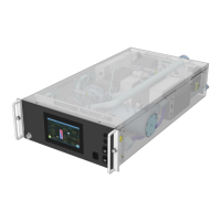
Neptune DWC RM100 in-rack Coolant Distribution Unit
T4 Secondary Temperature Sensor Fault
Reading from Secondary return temperature sensor T4 is outside the normal range of 5 to 74°C (41 to
165°F) or disconnected.
Check sensor connections to the control board, check in-line connections, replace sensor.
T5 Primary Temperature Sensor Fault
Reading from Primary return temperature sensor T5 is outside the normal range of 5 to 74°C (41 to
165°F) or disconnected.
Check sensor connections to the control board, check in-line connections, replace sensor.
RH Relative Humidity Sensor Fault
Reading from Room humidity sensor RH is outside the normal range of 5 to 100% RH or disconnected.
[Note: if in Fixed Set Point + DW Offset mode, unit will revert to Fixed Set Point mode – default 18°C
(65°F)].
Check sensor connections to the control board, check in-line connections, replace sensor.
PS1 Secondary Pressure Sensor Fault
Reading from Secondary return pressure sensor PS1 (‘Fill’ pressure) is outside the normal range of -1
to 8 bar (-15 to 116 PSI) and min/max values only will be displayed. [Note: for DP control, if system
differential pressure is not valid, then pump speed will remain at last know demand].
Check sensor connections to the control board, check in-line connections, replace sensor.
PS2 Secondary Pressure Sensor Fault
Reading from Secondary filter outlet pressure sensor PS2 is outside the normal range of -1 to 8 bar (-
15 to 116 PSI) and min/max values only will be displayed [Note: if filter differential pressurePS1-PS2 is
not valid, then pump speed will remain at last know demand].
Check sensor connections to the control board, check in-line connections, replace sensor.
PS3 Secondary Pressure Sensor Fault
Reading from Secondary supply pressure sensor PS3 is outside the normal range of -1 to 8 bar (-15 to
116 PSI) and min/max values only will be displayed [Note: for DP control, if system differential
pressure PS3-PS1 is not valid, then pump speed will remain at last know demand].
Check sensor connections to the control board, check in-line connections, replace sensor.
Secondary Flow Meter Sensor Fault
Secondary flow meter output is below 4mA.
Check sensor connections to the control board, check in-line connections, replace sensor.
Primary Flow Meter Sensor Fault
Primary flow meter output is below 4mA.
Check sensor connections to the control board, check in-line connections, replace sensor.
The SD card has either been removed or physically damaged.
Leak Fault / Water Make-up Empty
Fill pump has been running for more than 1 minute (default), when level sensor is made, but
minimum system pressure level has not been achieved. Also activated when level switch remains
open and system pressure has not been achieved (accompanied by an ‘A16 - Insufficient Water Level’
alarm).
Check the make-up water container is full, tubes are free of air locks, container is properly connected
and fill pump is operational. Check system for leaks.
 Loading...