CDU Operating & Maintenance Guide Page 32
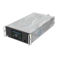
Neptune DWC RM100 in-rack Coolant Distribution Unit
Leak Shutdown / Insufficient Water
On Initial Start-up – if level sensor is not made, fill pressure has not been achieved & fill pump has
been running for more than 1 minute, then unit will not start or shutdown immediately.
While Unit is Running – This will be in conjunction with a ‘A34 – Level Sensor – No Water Detected’
alarm (refer to A34 for detail). If level sensor is not made and flow of DP is < 50% of flow/DP setpoint,
then unit will shut down after a 1 sec. delay
Check that water make-up container is properly connected (or filling wand is fully immersed, if used).
Check system for leaks. Check there is no trapped air in fill pump hoses and system is fully vented.
Check auto air vents are open.
Pump 1 is drawing excessive current, or speed controller has been subjected to over/under voltage.
Alarm will only appear after speed controller has gone into fault condition; Pump 2 will then run.
Pump 2 is drawing excessive current, or speed controller has been subjected to over/under voltage.
Alarm will only appear after speed controller has gone into fault condition; Pump 1 will then run.
Secondary Pump Flow Shutdown
An A17 & A18 – Pump Fault and/or an A43 & A44 – Pump Comms Fault have been generated.
Check running current of pumps, check speed controllers for faults. Faults will need to be rectified &
alarms cleared before unit can be started again
Feedback signal from control valve is more than 10% (default) adrift from demand signal (sampled
every 15 mins (default) and allowing for 40 second (default) positioning time).
Check the wiring connections to the actuator. Try to set the actuator position using the ‘Auto
Overrides’ function. Check the cooling valve demand % and feedback signals (Diagnostics AO04 &
UI13)
Will only activate when valve demand is at 100%, ‘A25 - Secondary Water High Temp’ alarm is active
and Primary water temperature is within specified limits (default 5 min. delay applies).
Check operation of control valve. Check primary water supply flow rate. Ensure system heat load does
not exceed the RM100 capacity (i.e. check that Primary flow is sufficient for heat load – refer to
RM100 Application & Planning Guide
Primary Water Low Temperature
Primary water temperature has dropped below the default 4°C (40°F) threshold. Alarm will cancel
when temperature rises to 5°C (42°F) or more (default 2 min. delay applies).
Check chilled water supply
Primary Water High Temperature
Primary water temperature has risen above the default 11°C (52°F) threshold. Alarm will cancel when
temperature falls to 10°C (50°F) or less (default 2 min. delay applies).
Check chilled water supply
Secondary Water Low Temperature
Secondary water temperature has dropped by more than 2°C (4°F) below set point (default). Alarm
will cancel when temperature rises to 1°C (2°F) below set point or higher. If Dew Point Offset is active,
then this alarm will only activate when at or below dew point for a period of 3 minutes or more
(default 2 minute delay applies).
Check operation of control valve
 Loading...
