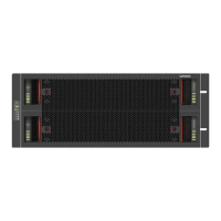
Table 3. 5U84 Enclosure Variants
Product Configuration PSUs ESMs Cooling Modules
D3284
12Gb/s direct dock LFF SAS
2 2 5
The 2U Enclosure Core Product
The design concept is based on an enclosure subsystem together with a set of plug-in modules. A typical
enclosure system (as supplied) comprises:
• An enclosure chassis comprising:
– A midplane PCB.
– An integral, front flange-mounted operator’s (Ops) panel.
• Up to two 580 W, 100-240 V AC power cooling modules (PCMs). See Figure 23 “580W Power Cooling
Module ” on page 21.
• Up to two ESMs: two SBB (Storage Bridge Bay) compliant interface bays.
• Up to 24 drive carrier modules with drives installed. Where appropriate, drive carriers include an
interposer card (refer to Figure 12 “5U84 Enclosure System – front view ” on page 10).
Note: Dummy drive carrier modules must be put in all empty drive bays.
• A rail kit for rack mounting.
Note: The module quantities quoted above are the maximum that a 2U24 enclosure can hold. Figure 14
“Module Locations (2U12)” on page 12 and Figure 15 “Module Locations (2U24)” on page 13 show the
module and major component locations of the 2U enclosures.
Important: To ensure correct airflow and cooling, all PSU bays and cooling module bays must contain a
functioning unit. If the enclosure is run with a single ESM, the other ESM bay must be filled with a blank
module.
Figure 14. Module Locations (2U12)
12 Lenovo Storage D1212/D1224/D3284Hardware Installation and Maintenance Guide
 Loading...