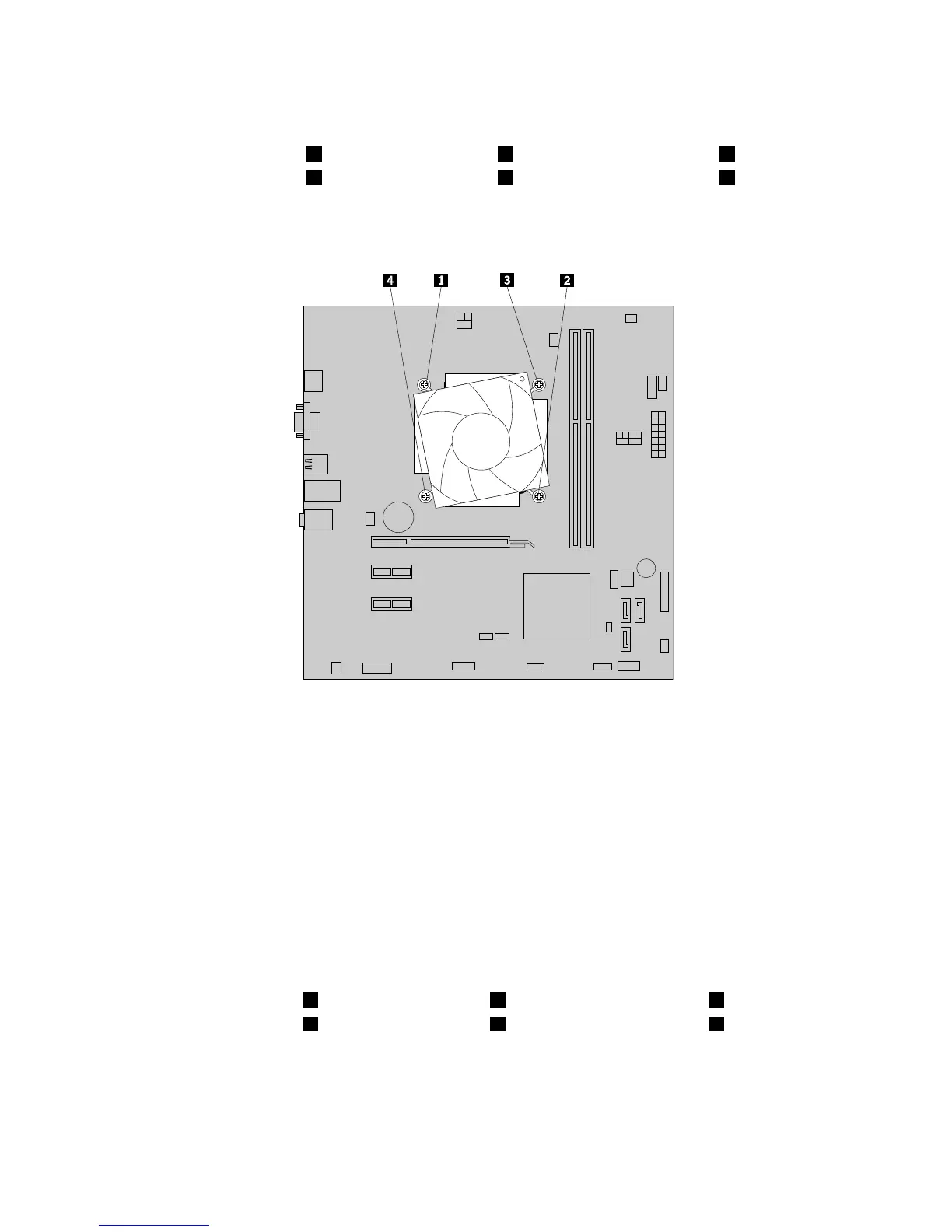
6.Followthissequencetoremovethefourscrewsthatsecuretheheatsinkandfanassemblytothe
systemboard:
a.Partiallyremovescrew1,thenfullyremovescrew2,andthenfullyremovescrew1.
b.Partiallyremovescrew3,thenfullyremovescrew4,andthenfullyremovescrew3.
Note:Carefullyremovethefourscrewsfromthesystemboardtoavoidanypossibledamagetothe
systemboard.Thefourscrewscannotberemovedfromtheheatsinkandfanassembly.
Figure42.Removingtheheatsinkandfanassembly
7.Liftthefailingheatsinkandfanassemblyoffthesystemboard.
Notes:
a.Youmighthavetogentlytwisttheheatsinkandfanassemblytofreeitfromthemicroprocessor.
b.Whenhandlingtheheatsinkandfanassembly,donottouchthethermalgreaseonthebottom
oftheheatsinkandfanassembly.
8.Placethenewheatsinkandfanassemblyonthesystemboardsothatthefourscrewsarealignedwith
thecorrespondingholesinthesystemboard.
Note:Positionthenewheatsinkandfanassemblysothattheheatsinkandfanassemblycableis
towardthemicroprocessorfanconnectoronthesystemboard.
9.Followthefollowingsequencetoinstallthefourscrewstosecurethenewheatsinkandfanassembly.
Donotover-tightenthescrews.
a.Partiallytightenscrew1,thenfullytightenscrew2,andthenfullytightenscrew1.
b.Partiallytightenscrew3,thenfullytightenscrew4,andthenfullytightenscrew3.
10.Connectthenewheatsinkandfanassemblycabletothemicroprocessorfanconnectoronthesystem
board.See“Locatingpartsonthesystemboard”onpage13.
11.Lowerandpositiontheheatsinkfanductonthetopoftheheatsinkandfanassemblyuntilitsnaps
intoposition.
62ThinkCentreE73UserGuide