3.Makesurethatthecablesareroutedcorrectlybeforereinstallingtheservercover.Keepcablesclearof
thehingesandsidesoftheserverchassistoavoidinterferencewithreinstallingtheservercover.
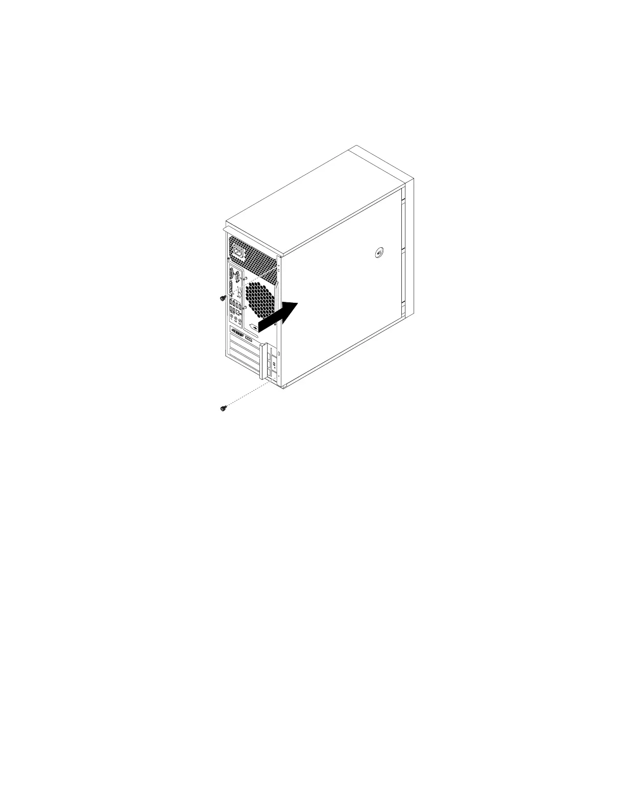
4.Positiontheservercoveronthechassissothattherailguidesonthebottomoftheservercoverengage
therailsonthechassis.Then,slidethecovertothefrontoftheserveruntilitsnapsintoposition.
Figure69.Reinstallingtheservercover
5.Installthescrewstosecuretheservercover.
6.Locktheservercoverifyouhaveaservercoverlock.See“Integratedcablelock”onpage85or
“Padlock”onpage85
.
7.Reconnecttheexternalcablesandpowercordstotheserver.See“Frontviewoftheserver”onpage
10and“Rearviewoftheserver”onpage11.
8.Dependingonthepartsyouinstalledorreplaced,youmightneedtoconfirmtheupdatedinformationin
theSetupUtilityprogram.RefertoChapter5“Configuringtheserver”onpage19.
Note:Inmostareasoftheworld,LenovorequiresthereturnofthedefectiveCustomerReplaceableUnit
(CRU).InformationaboutthiswillcomewiththeCRUorwillcomeafewdaysaftertheCRUarrives.
Connectingthecables
Attention:Topreventdamagetoequipment,connectthepowercordsaftercompletingtheparts
replacement.
Iftheservercablesandconnectorpanelhavecolor-codedconnections,matchthecolorofthecableend
withthecoloroftheconnector.Forexample,matchabluecableendwithabluepanelconnector,ared
cableendwitharedconnector,andsoon.See“Rearviewoftheserver”onpage11
foranillustrationofthe
I/Oconnectorsontherearoftheserver.
84ThinkServerTS140UserGuide