Configuration
7-100
48XX/49XXSHB0399
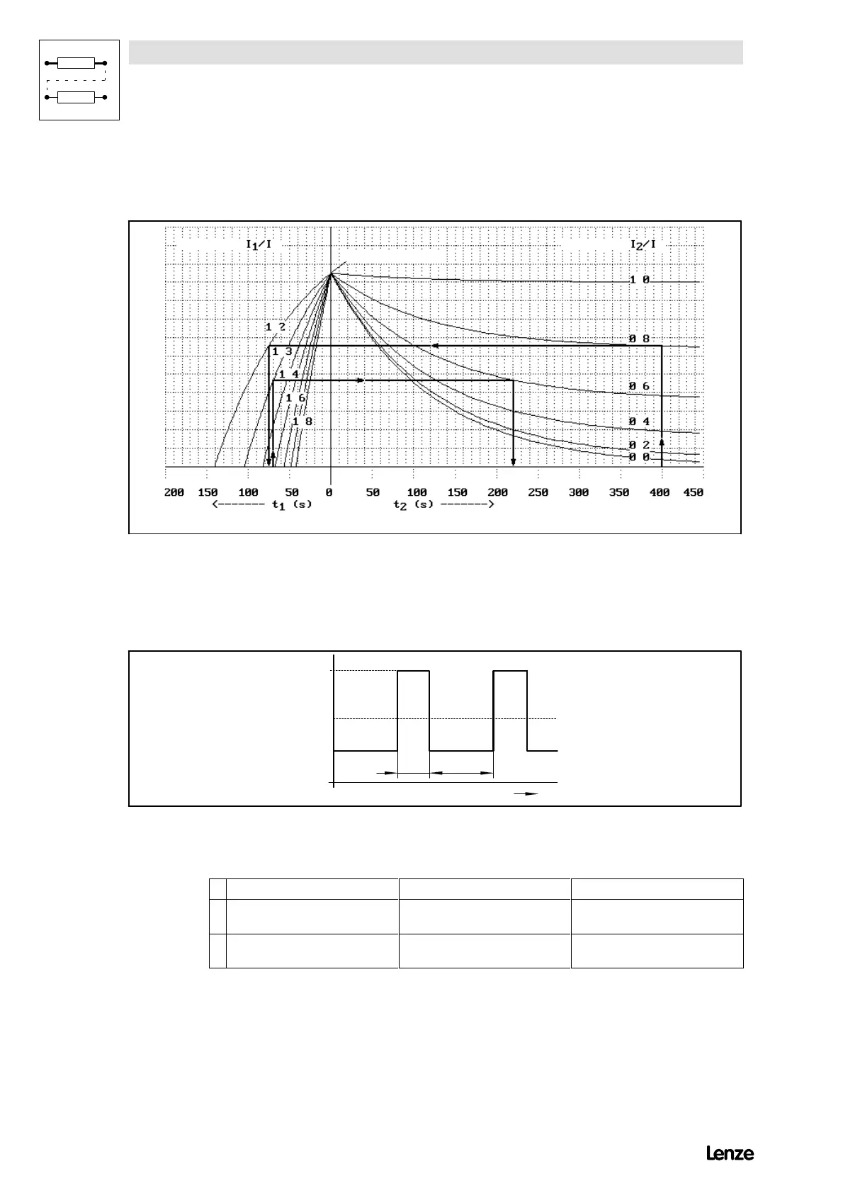
7.7.2 Overload monitoring for the controller (I¼t monitoring)
The I¼t monitoring is designed for 150 % rated current.
4900Str083
Param eter
Param eter
TRIP
O verload tim e
R ecovery tim e
.
.
.
.
.
.
.
.
.
.
.
r
r
FIG 7-56 Overload diagram for 48XX/49XX controllers
The parameter I
1
/I
rated
depends on the controller size. The ratio between
maximum current and rated armature current is indicated in chapter 3.3.
4900Str084
I
t
1
I
ra te d
I
2
t
1
t
2
FIG 7-57 Possible current flow when using the full overload capacity of 48XX/49XX controllers
Examples for overload diagrams in FIG 7-56:
given required Result from diagram
Overload, I
1
=1.3ôI
rated
Overload time, t
1
= 70s
-I
2
= ? (basic load)
-t
2
= ? (recovery time)
I
2
=0.6ôI
rated
t
2
> 220 s
2. Basic load, I
2
=0.8ôI
rated
,
Recovery time t
2
400s
-I
1
=?(overload)
-t
1
=?(overloadtime)
I
1
=1.2ôI
rated
t
1
$75s
For safety reasons, the ”I¼t monitoring” is rated for continuous load with rated
armature current during mains switch-on.