Commissioning
5-2
48XX/49XXSHB0399
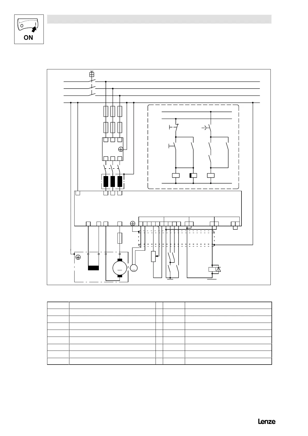
Wiring recommendation for speed control with tacho
Z1
K1
F’1...F’3
L
K
F’’1...F’’3
Q1
L1
L2
L3
PE
L1 L2 L3
L’1L’2L’3
L1 L2 L3PE
I K 20B
F’4
M
IK AB
M1
21 28 3940 59 90FE8 97
X1 X2 X3 X4
4900
A
Ctrl.
enable
CW
nset
T
43 5 22
CCW
K2
A4
K3
QSP nact = 0
S1
S2 K2
K2 K2.1 K1
K2.1
K2K3
K1
td
td > tbr.
L11
L10
L20
4900Str024
FIG 5-1 Flow chart section: Speed control with tacho
F’’1...F’’3
Cable protection fuse L11 ”Emergency stop” cable
F’1...F’3 Semiconductor fuse LK Mains choke
F’4 Armature fuse M1 Motor
K1 Mains contactor nset Setpoint potentiometer
K2 QSP relay CW CW rotation
K2.1 Delay timer Ctrl. enable Controller enable
K3 Motor standstill Q1 Main switch
CCW CCW rotation QSP Quick stop function
L10 Direct cable from the control cable ”ON” Z1 RFI filter
With a tacho voltage to ground: bridge terminals X1/4 and X1/5 and configure the
switch S4 on the control module for the operation with a tacho signal to ground
(chpt. 4.3.4.1).