Installation
4-21
48XX/49XXSHB0399
4.3.5 Feedback systems
Several feedback systems can be connected to the controller and configured:
( Armature voltage control
( DC tacho feedback
( Resolver feedback
( Encoder feedback
- Incremental encoder TTL
- Incremental encoder HTL
DC tacho feedback
Tacho signals are connected via term. 3/4 of terminal block X1. The controller
processes rated tacho voltages of 10...180V (chapter 4.3.5.1).
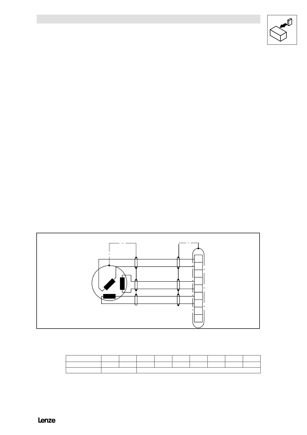
Resolver feedback (X7)
( 2-pole resolver (V = 10 V, f = 5 kHz)
( Connection to a 9-pole Sub D socket X7
- We recommend to use the pre-cut Lenze system cable
(see chapter 13.3).
( Resolver cable and resolver are monitored for wire breakage (fault message
”Sd2”)
+REF
-REF
+COS
-COS
+SIN
-SIN
1
2
3
4
5
6
7
8
9
X7
l
max
=50m
4900Str015
FIG 4-15 Resolver connection (9-pole Sub D socket)
Pin assignment of socket X7:
Pin 1 2 3 4 5 6 7 8 9
Signal +REF -REF GND +COS -COS +SIN -SIN --- ---
Cross section 0.5 0.14