Installation
4-20
48XX/49XXSHB0399
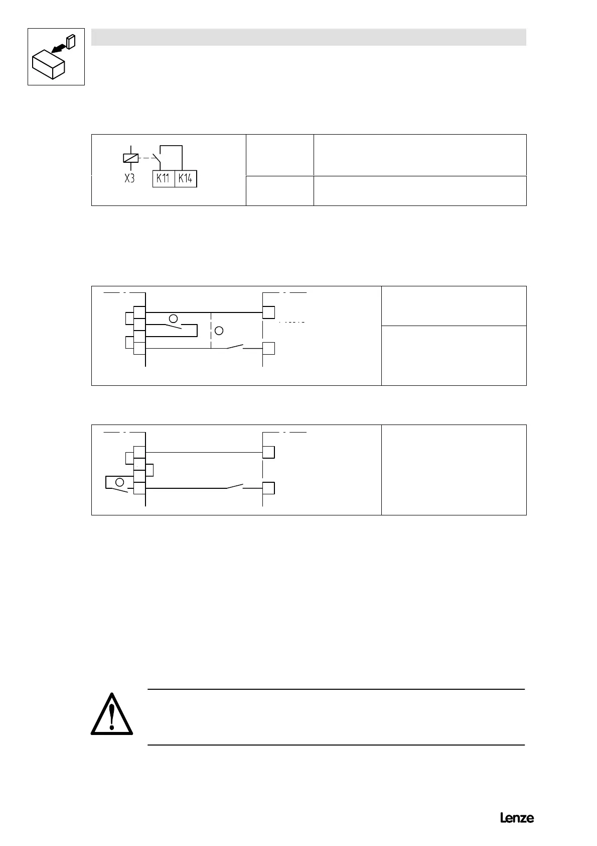
Relay output
Ter minal Use
(factory setting)
4900Str063
K11, K14 Floating relay output, contact load capacitiy: 50V / 0.5A (TRIP)
Additional digital inputs and outputs with 4X08...4X13
The controllers 4X08...4X13 are equipped with additional control terminals to
monitor the fuses. The following current flow charts show the factory setting of the
internal wiring and give suggestions on how to include an external fuse monitoring.
86
+ Vcc15
20
1
4908LP
4902MP
¥
External fuse monitoring
88
89 28
Ctrl. enable
2
4900Str013
¦
Without external fuse monitoring, terminal
20 can be directly connected with the
switch Ctrl. enable.
FIG 4-13 4808...4809 and 4908...4909
86
+ Vcc15
87
20
4911LP
4902MP
¥
Internal fuse monitoring
88
89 28
Ctrl. enable
1
4900Str_01
FIG 4-14 4811...4813 and 4911...4913
For monitoring, the terminals 86 and 89 should be connected in series with the
controller enable contact Ctrl. enable.
( For internal voltage supply (15 V), bridge the following terminals:
- X2/20 to 86
- X2/28 to 89
( For external voltage supply (24 V):
- Apply supply voltage to terminal 86.
- Bridge terminals 28 and 89.
Danger! (especially for hoist applications)
Please observe when connecting the fuse monitoring:
No torque is generated when the controller is inhibited.