Installation
4-5
48XX/49XXSHB0399
4.3 Connection
Connection between controller and motor
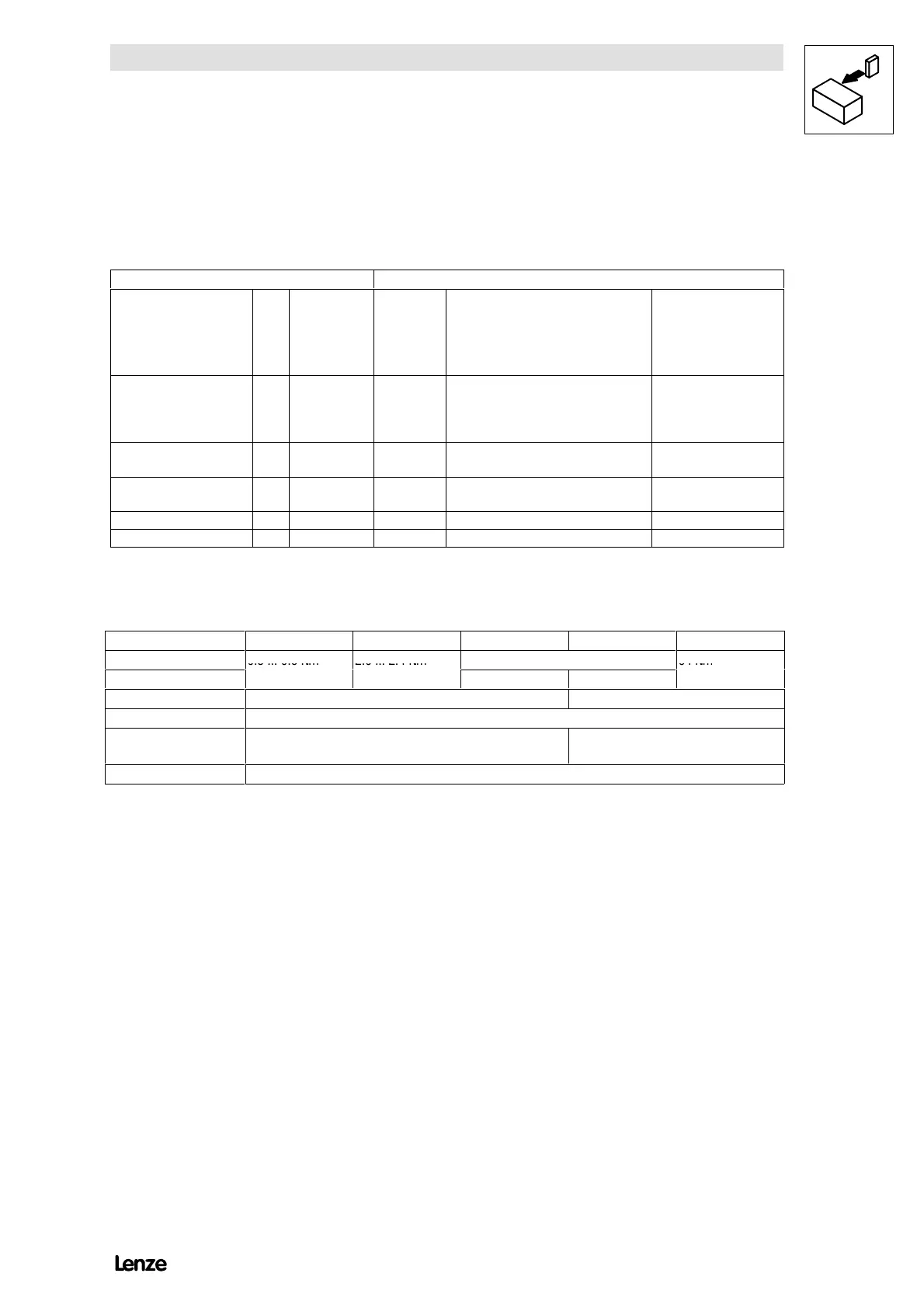
Lenze controller Motor (to DIN 42017/VDE 0530 part 8)
Function Ter minal Termin al Others Motor type
Armature voltage
Excitation voltage
+
-
+
-
A
B
I
K
1B1
2B2
F1
F2
A1
B2, A2
F5, (for higher connection voltages)
F2
DC motor
uncompensated with
commutating winding
Armature voltage
Excitation voltage
+
-
+
-
A
B
I
K
1C1
2C2
F1
F2
A1
C2
F5, (for higher connection voltages)
F2
DC motor
compensated with
commutating winding
Armature voltage +
-
A
B
A1
A2
Permanent-magnet
motor
DC tacho +
-
3
4
2A1
2A2
Te mp . s wi t c h S1, S2
Thermal contact T1, T2
Screw-tightening torques
Type 4902 4903 - 4904 4905 - 4907 4X08 - 4X09 4X11 - 4X13
L1,L2,L3,A,B
0.5 ... 0.6 Nm 2.0 ... 2.4 Nm
37 Nm
1)
64 Nm
1)
A, B
37 Nm
1)
15 ... 20 Nm
L1.1, L3.1, I, K 0.5 ... 0.6 Nm 1.2 ... 1.5 Nm
L1.2, L2.2, L3.2 0.5 ... 0.6 Nm
L1.3, L2.3, L3.3, 86 - 89 - 0.5 ... 0.6 Nm
Terminal strip X1 - X4 0.5 ... 0.6 Nm
1) Rated tightening torque for the connection of terminal ends to busbars
(VDE 0220 part 1/11.71)
When continued with busbar see DIN 43673 part 1/02.82
The following circuit diagrams show the electrical wiring of the power connections.