Installation
4-22
48XX/49XXSHB0399
The resolver signal or encoder signal can be output for following drives at the digital
frequency output X8.
( Connection as shown in the connection diagrams:
- Use cables twisted and screened in pairs.
- Connect both screen ends.
- Use cable cross-sections indicated.
( The feedback system can be activated under C005.
( If resolvers are used which are not specified by Lenze are used, contact
your Lenze representative.
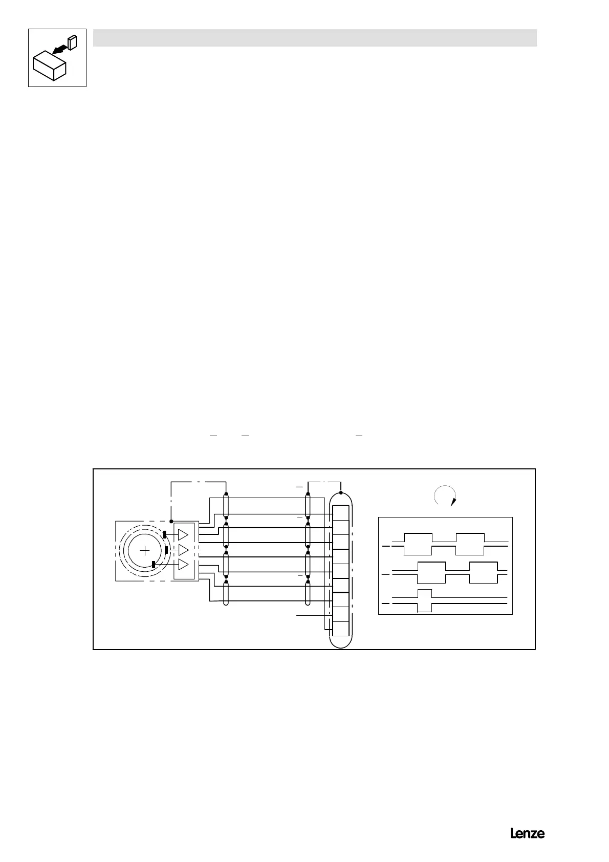
Incremental encoder feedback
( Incremental encoders with two 5 V complementary signals electrically
shifted by 90(TTL encoders) or HTL encoders can be connected.
( Connection to a 9-pole Sub D socket X5 or X9, depending on the
configuration of C005
- Maximum input frequency: 420 kHz with TTL encoder
100 kHz with HTL encoder
- Current consumption per channel: 6 mA
( With HTL signal:
- If there is no inverse track available, the
inputs A
and B (with zero track also Z ) must be connected to the
encoder supply potential.
B
A
VE9
GND
Z
Z
1
2
3
4
5
6
7
8
9
A
B
A
B
A
B
Z
Z
l
max
=50m
4900Sttr016
FIG 4-16 Incremental encoder connection (9-pole Sub D socket)