Installation
4-7
48XX/49XXSHB0399
4900Str128
Z1
K1
F '1 ...F '3
L
K
F ''1 ...F ''3
L1 L2 L3
L1 L2 L3
L'1 L'2 L'3
L1 L2 L3
PE B
F'4
M
M1
A
I
K
A
B
S1 S2
J
I
K
L1.2 L2.2 L3.2
PE
L2.3L1.3
FF32A
600V
4908LP
4902VP
F4
F3
M 0,5A 500V
F1 F2
BR5
BR3
BR4
PE
V
mains
= 3 4 0 ... 460 V ~ ±0 % 50 ... 6 0 H z
F5
F6
FF16A 500V
F7
L3.1L1.1
M
~
95
96
V = 200...240 V~ 50...6 0 H z
0,6A
L
K2
L
K2
F''5F''4
Z2
L1 N
L1 N
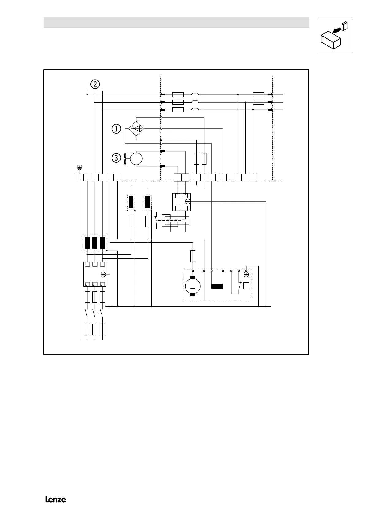
FIG 4-4 Power connection of controllers 4X08 to 4X09
K1 Mains contactor
F’1...F’4 Semiconductor fuses for the protection of controllers
F’’1...F’’5 Line protection fuses
L
K
Commutating choke (mains choke)
Z1 RFI filter
Z2 RFI filter for separate fan supply
BR3 - BR5 0W wire bridge
¥
Field controller
¦
Power stage
§
Fan