Technical Data
8250BA0903 3-3
3.3 Rated data
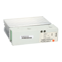
3.3.1 Brake units
Type EMB8251-E EMB8252-E EMB8253-E
Order
no.
EMB8251-E EMB8252-E EMB8253-E
Supply voltage V
N
270 ¼ 400 V DC 270 ¼ 750 V DC 270 ¼ 750 V DC
Threshold V
Z
375 V DC 725 V DC 725 V DC
Peak current 5.4 A DC 2.7 A DC 15 A DC
Max. continuous current 0.2 A DC 0.1 A DC 7.5 A DC
Peak braking power at V
Z
2kW
1)
2kW
1)
11.2 kW
2)
Continuous braking power at V
Z
70 W 70 W 5.6 kW
Min. brake resistance (internal resistor) (internal resistor) 47 Ω ± 10%
Max. energy (min. 5 min break) 20 kWs 20 kWs (external resistor)
Power derating 40 °C<T<50°C: 2%/K
1000 m a.m.s.l. < h < 4000 m a.m.s.l.: 5%/1000 m
Weight 1.3 kg 1.3 kg 1.1 kg
1)
max. 10 s with switch-on cycle 3 %
2)
max. 60 s with switch-on cycle 50 %
3.3.2 Assignment table for brake resistors
The assignment depends on the motor power and is effective up
to the indicated limit value.
Motor power Recommended Lenze brake resistor
Order no. Resistor Peak braking power Thermal capacity
kW Ω kW kWs
<0.75 ERBM470R100W 470 1.0 15
<1.5 ERBM370R150W 370 1.5 22,5
<2.2 ERBM240R200W 240 2.0 30
<3.0 ERBD180R300W 180 3.0 45
<4.0 ERBD100R600W 100 5.5 90
<5.5 ERBD082R600W 82 6.5 90
<7.5 ERBD068R800W 68 8.0 120
< 11.0 ERBD047R01K2 47 11.5 180
The resistors are designed for a cycle of:
• max. 15 s braking at peak braking power
• min. 150 s release time after braking

 Loading...