Installation
4-26
SHB9300CRV EN 2.0
System bus connection (X4)
K1
K1
L3
N
PE
L1
L2
U
V
W
L1 L2
L3
F1
932X - 933X
PE
+UG -UG
PE
Z1
K1
U
V
W
L1 L2 L3
932X - 933X
PE
+UG -UG
PE
Z1
F1
ON
OFF
28
A4
PE
28
A4
K1
RFR
PE
U
V
W
L1 L2 L3
932X - 933X
PE
+UG
-UG
PE
Z1
F1
28
A4
PE
K1
RFR
K1
RFR
GND
HI
LO
GND
HI
LO
RA2
GND
HI LO
RA1
F2 F3 F2 F3 F2 F3
K35.0123
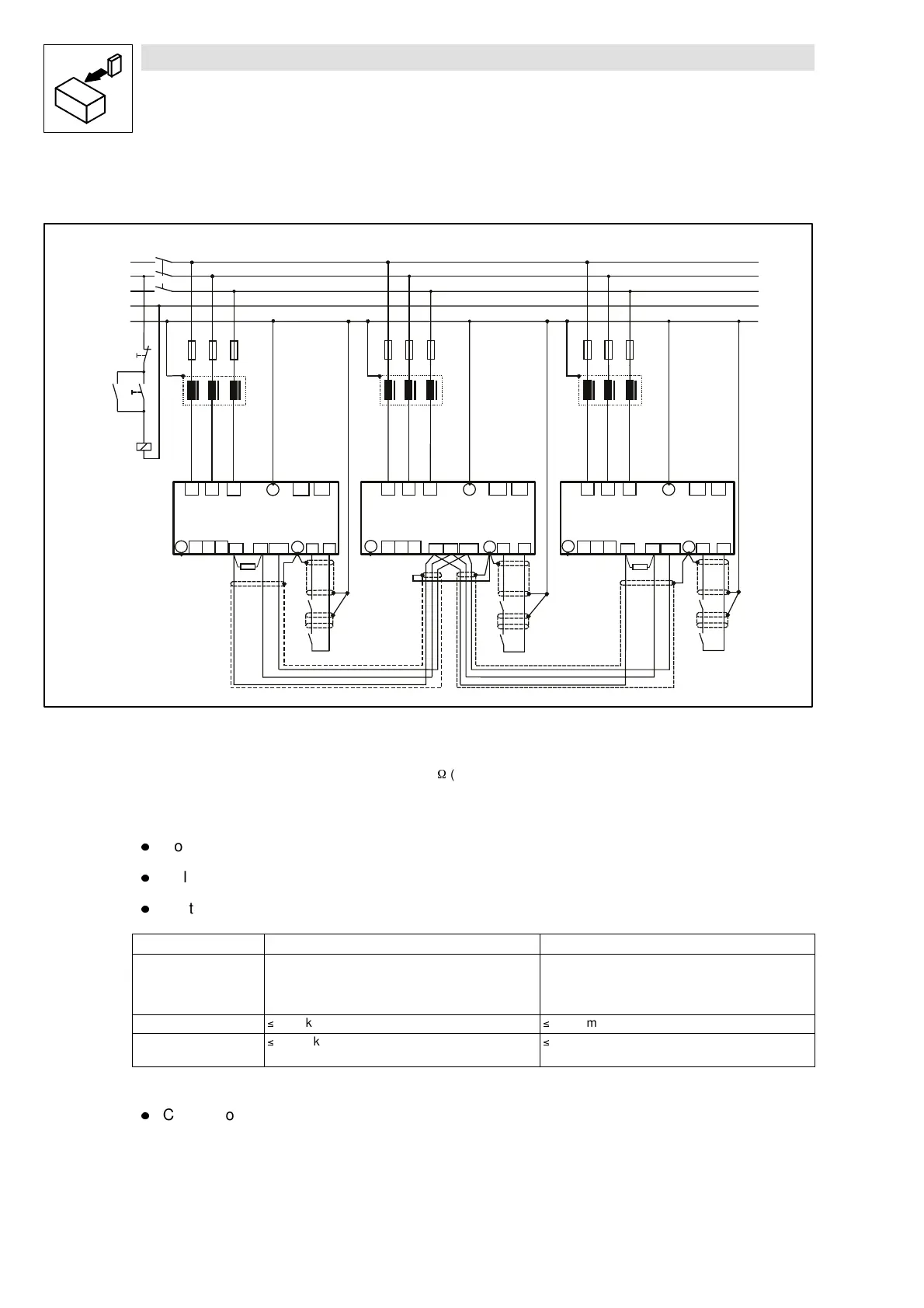
Fig. 4-13 Wiring of the system bus
RA1, RA2 Bus terminating resistors 120
W
(included in the accessory kit)
l
Connection via pluggable screw terminals (double terminals can be used).
l
Only connect terminals of the same designation.
l
Features of the signal cable:
Total cable length up to 300 m 300 m to 1000 m
Cable type LIYCY2x2x0.5mm
2
twisted pair with screening
Pair 1: CAN-LOW (LO) and CAN-HIGH (HI)
Pair 2: 2*GND
CYPIMF2x2x0.5mm
2
twisted pair with screening
Pair 1: CAN-LOW (LO) and CAN-HIGH (HI)
Pair 2: 2*GND
Cable resistance
40 Ω/km
40 Ω/km
Capacitance per unit
length
130 nF/km
60 nF/km
l
Connection of the bus termination resistors:
– Connect one resistor 120 W to the first and one to the last bus participant.
– On the 93XX controller the resistor can be screwed directly under the terminals X4/HI and
X4/LO.