RG-SFMOD 16
Drive Control & Communication
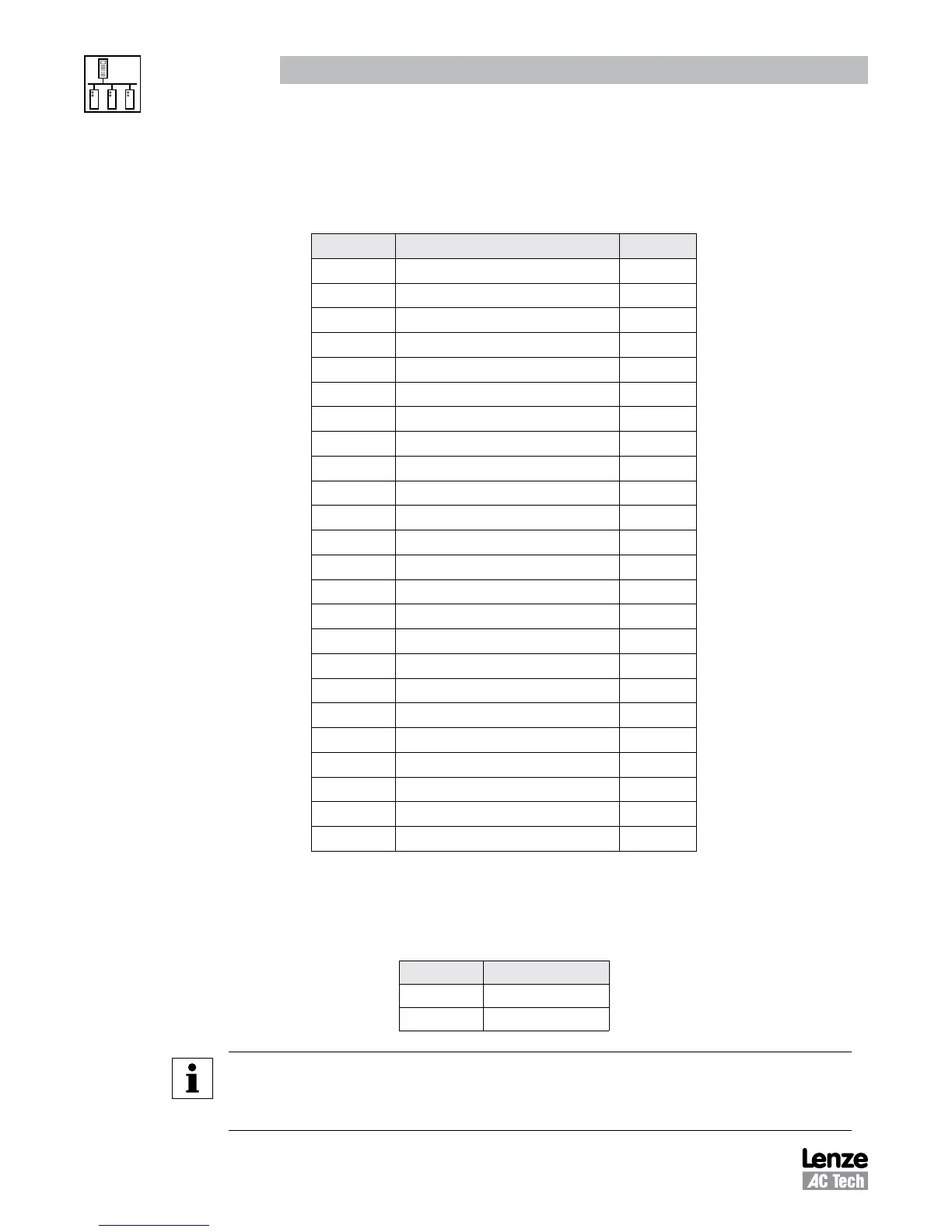
5.4.7 Present Fault - Registers #24 & 29
Table 15 lists the Present Fault (Register #24 byte D6H of Register #29 DH)
Table 15: Present Fault
Setting Fault Display
0 NO FAULT
1 OUTPUT (TRANSISTOR) FAULT “OF”
2 HIGH DRIVE TEMPERATURE “AF”
3 HIGH DC BUS VOLTAGE “HF”
4 LOW DC BUS VOLTAGE “LF”
5 THERMAL OVERLOAD “PF”
CONTROL FAULT “CF”
7 EXTERNAL “EF”
8 OEM FAULT “GF”
9 START ERROR “UF”
10 INTERNAL1 (EPM) “F1”
11 INTERNAL2 “F2”
12 INTERNAL3 “F3”
13 INTERNAL4 “F4”
14 INTERNAL5 “F5”
15 INTERNAL6 “F6”
16 INTERNAL7 “F7”
17 INTERNAL8 “F8”
18 INTERNAL9 “F9”
19 INTERNALo “Fo”
20 SINGLE PHASE FAULT “SF”
21 INCOMPATIBILITY FAULT “cF”
22 DYNAMIC BRAKE OVERHEATED “dF”
23 SERIAL LINK FAULT “JF”
5.4.8 Commanded Rotational Direction - Registers #24 & 29
Table 16 lists the Commanded Rotational Direction (Register #24 byte D6L or Register #29 DL)
Table 16: Commanded Rotational Direction
Setting Direction
0 FORWARD
1 REVERSE
NOTE 4d - Commanded Rotational Direction
Register NOT used on SCF drives prior to software version 48, revision 7 (4807) and
software version 57, revision 3 (5703).
 Loading...